Материал: Строительная механика и сопротивление материалов. Сафронов В.С., Ефрюш
СОДЕРЖАНИЕ
СТРОИТЕЛЬНАЯ МЕХАНИКА И СОПРОТИВЛЕНИЕ МАТЕРИАЛОВ
Кирсанов М. Н, Бука-Ваиваде К. |
|
Аналитические выражения частот малых колебаний балочной фермы |
7 |
с произвольным числом панелей ……………………………………………………... |
|
Бойко А. Ю., Ткачук Г. Н. |
|
Вывод формул зависимости прогиба плоской шарнирно-стержневой рамы |
|
от числа панелей в системе символьной математики MAPLE …………………….. |
15 |
Тимофеева Т. А. |
|
Формулы для расчет прогиба плоской решетчатой рамы |
|
с произвольным числом панелей …………………………………………………….. |
26 |
ПРИКЛАДНЫЕ ЗАДАЧИ МЕХАНИКИ |
|
ДЕФОРМИРУЕМОГО ТВЕРДОГО ТЕЛА |
|
Козлов В. А. |
|
Векторная форма метода конечных разностей в задачах теории тонких оболочек |
34 |
Несмеев Ю. А. |
|
Способ вычисления корней уравнений, связанных с цепной линией |
|
или с перевернутой цепной линией ………………………………………………….. |
44 |
РАСЧЕТ И ПРОЕКТИРОВАНИЕ |
|
МОСТОВ И ТРАНСПОРТНЫХ СООРУЖЕНИЙ |
|
Сафронов В.С., Осипов С.А., Мельхиор Н. |
|
Сопоставление надежности типового железобетонного пролетного строения |
|
автодорожного моста для российских и европейских нормативных временных |
|
нагрузок………………………………………………………………………………… |
51 |
Аверин А.Н., Рыдченко Д. Г., Провоторова М. В. |
|
Расчет неразрезной сталежелезобетонной балки на подвижную нагрузку |
|
с учетом раскрытия трещин…………………………………………………………… |
63 |
РАСЧЕТ И ПРОЕКТИРОВАНИЕ |
|
МЕТАЛЛИЧЕСКИХ КОНСТРУКЦИЙ |
|
Кузнецов Д. Н. |
|
Устойчивость состояния равновесия несущих конструкций в составе |
|
конечно-элементных систем ………………………………………………………….. |
75 |
РАСЧЕТ И ПРОЕКТИРОВАНИЕ |
|
ЖЕЛЕЗОБЕТОННЫХ КОНСТРУКЦИЙ |
|
Ефрюшин С.В., Юрьев В. В. |
|
Численное моделирование огнестойкости железобетонной плиты с помощью |
|
программного комплекса ANSYS ……………………………………………………. |
86 |
|
|
РАСЧЕТ И ПРОЕКТИРОВАНИЕ |
|
ОСНОВАНИЙ И ФУНДАМЕНТОВ ЗДАНИЙ И СООРУЖЕНИЙ |
|
Аль-Бухейти А. Я., Даниш А. Б., Леденев В. В., Савинов Я. В. |
|
Экспериментально-теоретические исследования перемещений близко |
|
расположенных фундаментов при действии плоской системы сил ……………….. |
93 |
Правила оформления статей ……………………………………………………….. |
108 |
5 |
|
CONTENT
STRUCTURAL MECHANICS
AND STRENGTH OF MATERIALS
M.N. Kirsanov, K. Buka-Vaivade |
|
Analytical expressions of frequencies of small oscillations of a beam truss with an arbitrary |
|
number of panels ……………………………………………………………………………… |
7 |
A.Yu.Boyko, G.N. Tkachuk |
|
Derivation of the formulas for the deflection of a flat hingеd-rod frame in the of symbol |
|
mathematics MAPLE system………………………………………………………………….. |
15 |
T.A. Timofeeva |
|
Formulas for calculating the deflection of a flat lattice frame with an arbitrary number |
|
of panels ……………………………………………………………………………………… |
26 |
APPLIED PROBLEMS OF MECHANICS |
|
OF SOLID BODY UNDER DEFORMATION |
|
V.A. Kozlov |
|
Vector form of finite difference method in the problems of thin shell theory…………………. |
34 |
Yu.A. Nesmeev |
|
Way of calculation of roots the equations connected with the chain line or with the turned |
|
chain line |
44 |
CALCULATION AND DESIGN |
|
OF BRIDGES AND TRANSPORT STRUCTURES |
|
V. S. Safronov, S. A. Osipov, N. Mel’khior |
|
Comparison of reliability of typical reinforced concrete span structure of the road bridge |
|
for Russian and European normative temporary loads………………………………………… |
51 |
A. N. Averin, D.G. Rydchenko, M.V. Provotorova |
|
Calculation of a continuous reinforced concrete beam for moving load taking into account |
|
crack opening displacement ………………………………………………………………….. |
63 |
CALCULATION AND DESIGN |
|
OF METAL STRUCTURES |
|
D. N. Kuznetsov |
|
Stability of the equilibrium state of bearing structures in composition |
|
of finite element systems……………………………………………………………………… |
75 |
CALCULATION AND DESIGN |
|
OF REINFORCED CONCRETE STRUCTURES |
|
S.V. Efryushin, V.V. Yuriev |
|
Numerical modeling of fire resistance of reinforced concrete plate using ANSYS software |
|
complex…………………………………………………………………………………………. |
86 |
CALCULATION AND DESIGN |
|
OF BASES AND FOUNDATIONS OF BUILDINGS AND STRUCTURES |
|
A.Y. Al-Bukhaiti, A.B. Danish, V.V. Ledenev, Y.V. Savinov |
|
Experimental and theoretical investigations of close-located foundations movements under |
|
the actions of plane force systems……………………………………………………………… |
93 |
Requirements for articles to be published…………………………………………………… 108
6
СТРОИТЕЛЬНАЯ МЕХАНИКА И СОПРОТИВЛЕНИЕ МАТЕРИАЛОВ
УДК 624.04:531.391.3
АНАЛИТИЧЕСКИЕ ВЫРАЖЕНИЯ ЧАСТОТ МАЛЫХ КОЛЕБАНИЙ БАЛОЧНОЙ ФЕРМЫ С ПРОИЗВОЛЬНЫМ ЧИСЛОМ ПАНЕЛЕЙ
М. Н. Кирсанов1, К. Бука-Ваиваде2
Национальный исследовательский университет ―МЭИ‖ Россия, г. Москва2
Рижский технический университет
Латвия, г. Рига
1Д-р физ.-мат. наук, тел.: +7(495)362-73-14; e-mail:c216@ya.ru
2 Аспирант, тел.:+37128877852; e-mail:karina.buka-vaivade@rtu.lv
Для вывода аналитической оценки нижней частоты собственных колебаний плоской статически определимой фермы рассмотрена инерционная модель фермы с массами, сосредоточенными в узлах ее нижнего пояса. Смещения грузов предполагаются вертикальными. Прогибы фермы под действием сосредоточенных сил, приложенных к узлам с массами и рассчитанные по формуле Максвелла – Мора, дают значения коэффициентов матрицы податливости фермы. Для оценки по методу Донкерлея требуются только диагональные элементы матрицы. Искомая оценочная формула получена методом индукции расчетом нижней границы первой частоты для отдельных ферм с последовательно увеличивающимся числом панелей. Это дает найти зависимость частоты колебаний фермы не только от ее размеров, но и от числа панелей. Коэффициенты формулы определяются из решения рекуррентных уравнений для элементов последовательностей, полученных из частных решений. В расчетах и анализе использована система компьютерной математики Maple.
Ключевые слова: ферма, первая частота колебаний, оценка Донкерлея, индукция, аналитическое ре-
шение,Maple.
The natural oscillation frequencies of the trusses required to assess the dynamics of the structure are calculated, as a rule, numerically [1-6]. In most cases, these solutions are used in optimization problems [7-9]. At the same time, a common and quite acceptable approximation is the truss model with concentrated masses at the nodes [10,11]. However, as practice shows [11-16], in such a formulation it is possible to obtain an analytical solution. The most demanded in practical calculations is the first, the lowest frequency of oscillations. The Donkerley method [17] makes it possible to derive a fairly simple formula for the lower bound of this value.
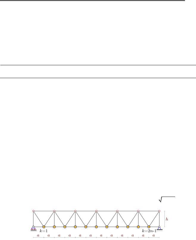
Consider a truss with a triangular lattice consisting of n identical panels (Fig. 1). Each panel in-
cludes two bars of lower chord of length a, two multidirectional struts of length c |
a |
2 |
h |
2 |
and struts |
|
|
|
|
|
|
||
of height h. In the truss the |
m 3n 5 bars, including three bars corresponding to the supports. |
|||||
Rice. 1. Trussat n=6. In the nodes of the lower chord are the masses mk , k 1,..., 2n 1
___________________________________
© Кирсанов М. Н., Бука-Ваиваде К., 2019
7
The mass of the truss is evenly distributed over the nodes of the lower chord of the truss: mk m, k 1,..., 2n 1. The estimation formula of Dunkerley gives a lower bound of the first natural frequency of the mass in the node
2
2n 11/ 1/ 2 k
k 1
.
(1)
Here is a notation
|
k |
|
for the oscillation frequency of a single mass
mk
, at the node k + 1 of
the lower chord, in the absence of all other masses. Numbering of knots is conducted from the left
support. The differential equation of mass
mk
m
oscillations of the second order has the form
|
|
|
my |
k |
d |
k ,n |
y |
k |
0, |
|
|
|
|
|
|
|
|
|
|
|
|||
where yk |
— vertical mass displacement, |
yk |
— acceleration, |
dk ,n |
— stiffness coefficient of mass with |
||||||
number k, n— number of panels in the truss. It follows that the frequency of oscillations of the load
|
k |
|
d |
k ,n |
/ m |
. The stiffness coefficient can be calculated through the flexibility coefficient by the |
|||||||
|
|
|
|
||||||||||
Maxwell-Mohr formula: |
|
|
|
|
|
|
|
||||||
|
|
|
|
|
|
|
m 3 |
S |
2 |
l |
|
|
|
|
|
|
|
|
|
|
|
|
|
|
|||
|
|
|
|
|
|
|
k,n 1/ dk ,n |
|
i,k i |
. |
|
|
|
|
|
|
|
|
|
|
EF |
|
|
||||
|
|
|
|
|
|
|
i 1 |
|
|
|
|||
|
|
|
|
|
|
|
|
|
i |
|
|
|
|
|
|
|
Here it is indicated Si,k |
— the forces in the bar numbered i 1,..., m 3 |
from the action of a |
||||||||
single vertical force applied to the node in which the load is located with the number k , |
li — the |
||||||||||||
length of the bar. It is accepted that the stiffness of all bars is the same: EFi EF . Three rigid sup-
port bars are not included.
The forces in the bars of the truss are determined by the program [11] in symbolic form. In the program by analogy with [11-17] coordinates of nodes and the scheme of connection of bars in nodes are entered. The origin is located in the left support:
x |
a(i 1), |
y |
0, i 1,..., 2n 1, |
|||
i |
|
|
i |
|
|
|
x |
2n 1 |
2a(i 1), |
y |
h, i 1,..., n 1. |
||
i |
|
|
|
i 2n 1 |
|
|
The lattice of the truss and its chord is formed by vectors Ni , i 1,..., m bers of the ends of the bars. The upper and lower chords are defined as follows:
Ni [i,i 1], i 1,..., 2n,
Ni 2n [i 2n 1,i 2n 2], i 1,..., n.
The grid (struts and braces) correspond to the vectors
containing the num-
N |
i 3n 1 |
[2i 1,i 2n 1], i 1,..., n 1, |
||
|
|
|
|
|
N |
i 4n 1 |
[2i,i 2n 1], N |
i 5n 1 |
[2i,i 2n 2], i 1,..., n. |
|
|
|
||
The system of equilibrium equations of nodes in projections on the axis is entered into the program written in matrix form. The matrix of the system consists of the guiding cosines of the forces. Odd rows of the matrix consist of projections of unit vectors of forces on the horizontal axis, even — on the vertical. Depending on the considered node with mass, to which a single force is applied, the distribution of forces on the bars is markedly different depending on the parity of the load number (Fig. 2,3). Compressionbars are highlighted in black, tension – in red. The thickness of the lines is proportional to the force.
8
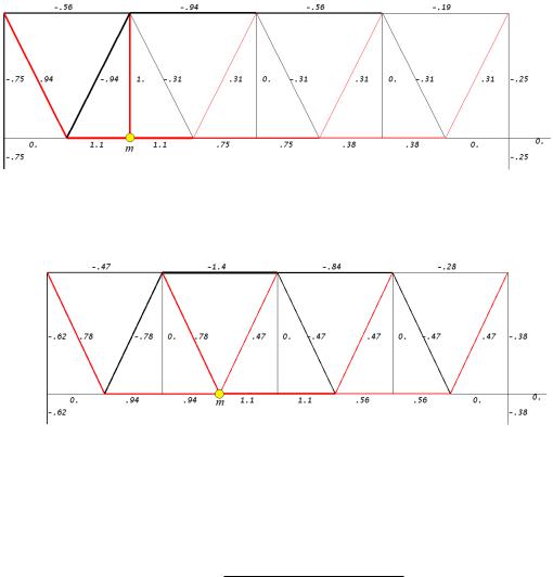
Fig. 2. The distribution of forces in the bars in fractions of 1 when considering the mass with an even numbern=4, k=2, a=3m, h=4m
Fig.3. The distribution of stresses in the bars when considering odd weight n=4, k=3, a=3m, h=4 m
Solving individual problems for trusses with a consistently increasing number of panels n=1, 2, 3,..., gives an expression of the flexibility coefficient from the action of a unit force in a node with mass k of the form
|
|
|
C |
a |
3 |
C |
|
|
c |
3 |
C |
h |
3 |
|
|
|
|
|
|
|
|
||||||
|
1,k ,n |
|
|
2,k ,n |
|
|
3,k ,n |
|
|
||||
|
|
|
|
|
|
|
|
|
|||||
|
k ,n |
|
|
|
|
2 |
2 |
EF |
|
|
|
||
|
|
|
|
|
|
n |
h |
|
|
|
|||
,
To obtain the dependence of the coefficients in this expression on the number of panels n and the number of nodes with massesk, the induction method is used. First, with a fixed number of nodes with masses coefficients are obtained for a different number of panels:
|
|
|
a3 |
c3 h3 |
|
|
14a3 |
6c3 5h3 |
|
|
55a3 15c3 13h3 |
|||||
|
1,1 |
|
|
|
|
, |
1,2 |
|
|
|
|
, |
1,3 |
|
|
, |
|
|
|
|
|
|
|
||||||||||
|
|
|
|
2h2 EF |
|
|
|
8h2 EF |
|
18h2 EF |
||||||
|
|
|
140a3 28c3 25h3 |
|
|
|
|
|
|
|||||||
1,4 |
|
|
|
|
|
|
|
,... |
|
|
|
|
|
|
||
|
|
32h2 EF |
|
|
|
|
|
|
|
|
|
|||||
|
|
|
|
|
|
|
|
|
|
|
|
|
|
|||
For the coefficient C1,1,n using the operator rgf_findrecur of the Maple system we obtain a recurrent equation for the common term
C |
4C |
6C |
1,1,n |
1,1,n 1 |
1,1,n 2 |
4C1,1,n 3
C1,1,n 4
.
The solution of this equation can be obtained using the rsolve operator:
C1,1,n 4n3 / 3 n2 n / 6.
Similarly, for k=1, we find the coefficients
9