Материал: m083700e

Внимание! Если размещение файла нарушает Ваши авторские права, то обязательно сообщите нам

116 • I/O Modules

4.5 Analog Output Modules

AO 0 - 20 mA

750-552 2 Channel, 0 - 20 mA

750-585 2 Channel, 0 - 20 mA, EEx i

AO 4 - 20 mA

750-554 2-channel, 4 - 20 mA

AO DC 0 - 10 V

750-550 2 Channel, DC 0 - 10 V

750-559 4 Channel, DC 0 - 10 V

750-560 2 Channel, DC 0 - 10 V, 8 Bit, 10 mA

AO DC ± 10 V

750-556 2 Channel, DC ± 10 V

750-557 4 Channel, DC ± 10 V

4.6 Special Modules

Counter Modules

750-404 Up / Down Counter, DC 24 V, 100 kHz

750-638 2 Channel, Up / Down Counter, DC 24 V/ 16Bit / 500 Hz

Frequency Measuring

750-404/ Frequency Measuring

000-003

Pulse Width Module

750-511 2-channel Pulse Width Module, DC 24 V, short-circuit-protected, high-side switching

Distance and Angle Measurement Modules

750-630 SSI Transmitter Interface

750-631 Incremental Encor Interface, TTL level squarewave

750-634 Incremental Encor Interface, DC 24 V

750-637 Incremental Encor Interface RS 422, cam outputs

750-635 Digital Pulse Interface

Serial Interfaces

750-650 Serial Interface RS 232 C

750-653 Serial Interface RS 485

750-651 TTY-Serial Interface, 20 mA Current Loop

750-654 Data Exchange Module

DALI / DSI Master Module

750-641 DALI / DSI Master Module

WAGO-I/O-SYSTEM 750

CANopen
I/O Modules • 117

AS interface Master Module

750-655 AS interface Master Module

Radio Receiver Module

750-642 Radio Receiver EnOcean

MP Bus Master Module

750-643 MP Bus (Multi Point Bus) Master Module

4.7 System Modules

Module Bus Extension

750-627 Module Bus Extension, End Module

750-628 Module Bus Extension, Coupler Module

DC 24 V Power Supply Modules

750-602 DC 24 V, passiv

750-601 DC 24 V, max. 6.3 A,without diagnostics, with fuse-holder

750-610 DC 24 V, max. 6.3 A, with diagnostics, with fuse-holder

750-625 DC 24 V, EEx i, diagnostics, with fuse-holder

DC 24 V Power Supply Modules with bus power supply

750-613 Bus power supply, 24 V DC

AC 120 V Power Supply Modules

750-615 AC 120 V, max. 6.3 A without diagnostics, with fuse-holder

AC 230 V Power Supply Modules

750-612 AC/DC 230 V without diagnostics, passiv

750-609 AC 230 V, max. 6.3 A without diagnostics, with fuse-holder

750-611 AC 230 V, max. 6.3 A with diagnostics, with fuse-holder

Filter Modules

750-624 Filter Module for field side power supply

750-626 Filter Module for system and field side power supply

Field Side Connection Module

750-614 Field Side Connection Module, AC/DC 0 ... 230 V

750-603 Field Side Connection Module, DC 24 V

750-604 Field Side Connection Module, DC 0 V

Separation Modules

750-616 Separation Module

750-621 Separation Module with Power Contacts

Binary Spacer Module

750-622 Binary Spacer Module

End Module

750-600 End Module, to loop the internal bus

WAGO-I/O-SYSTEM 750

CANopen

118 • CANopen

Description

5 CANopen

5.1 Description

CAN (Controller Area Network) was developed in the mid-eighties for data transmission in automobiles. The CAN specification defines the Data Link Layer which is the physical and data backup layer. The message structure is exactly described, however, nothing is said regarding the Application Layer. CAL, in the contrary, describes the Application Layer or the Meaning of the transmitted data. CAL is a general descriptive language for CAN networks and provides a large number of communication services.

CANopen is a networking concept based on the serial bus system CAN. CANopen is defined as a uniform application layer by the DS 301 specifications of the CIA (CAN in automation).

The network management provides a simplified start-up of the network. This network can be extended by the user as desired.

CAN is a Multimaster bus system. In contrast to other fieldbus systems, the modules connected to the bus are not addressed but the messages identified. Whenever the bus is free, the subscribers are allowed to send messages. Bus conflicts are solved in that the messages are assigned a certain priority. This priority is defined by the COB ID (Communication Object Identifier) and is clearly assigned to a communication object. The smaller the assigned identifier, the higher the priority. This also allows communication without the bus master group.

Each bus subscriber is solely decisive as to the point in time of data transmission. However, there is also a possibility to request other bus subscribers to send data. This request is performed via the so-called remote frame.

The CANopen specification (DS 301) defines the technical and functional features used to network distributed field automation devices.

Further information

CAN in Automation (CiA) provides further documents for their members in the Internet under:

can-cia.de

WAGO-I/O-SYSTEM 750

CANopen

CANopen • 119

Network Architecture

5.2 Network Architecture

5.2.1 Transmission Media

5.2.1.1 Type of Cable

A bus medium forms the basis for the physical connection of CAN.

With CAN, both the bus coupling and the bus medium are specified according to ISO 11898 (CAN High-Speed).

According to the cable specification, the Twisted-Pair medium (shielded cables twisted in pairs) with a wave resistance of 108...132 Ohm is recommended.

Twisted-Pair is low priced, convenient to use and permits simple bus type wiring.

The WAGO CANopen fieldbus nodes are intended for wiring using shielded copper wire (3x0.25 mm²).

Two important points have to be taken into consideration when designing the electrical bus medium:

the maximum bus length and

the required conductor cross section.

5.2.1.2Maximum Bus Length

The length of the bus is mainly limited by the signal running time and must, therefore, be adapted to the Baud rate:

Baud rate

Bus length

1 Mbit/s

30 m

800 kbit/s

50 m

500 kbit/s

100 m

250 kbit/s

250 m

125 kbit/s

500 m

50 kbit/s

1000 m

Table 5-1: Maximum bus length dependent on the set Baud rate

WAGO-I/O-SYSTEM 750

CANopen

120 • CANopen

Network Architecture

5.2.1.3 Required Conductor Cross Section

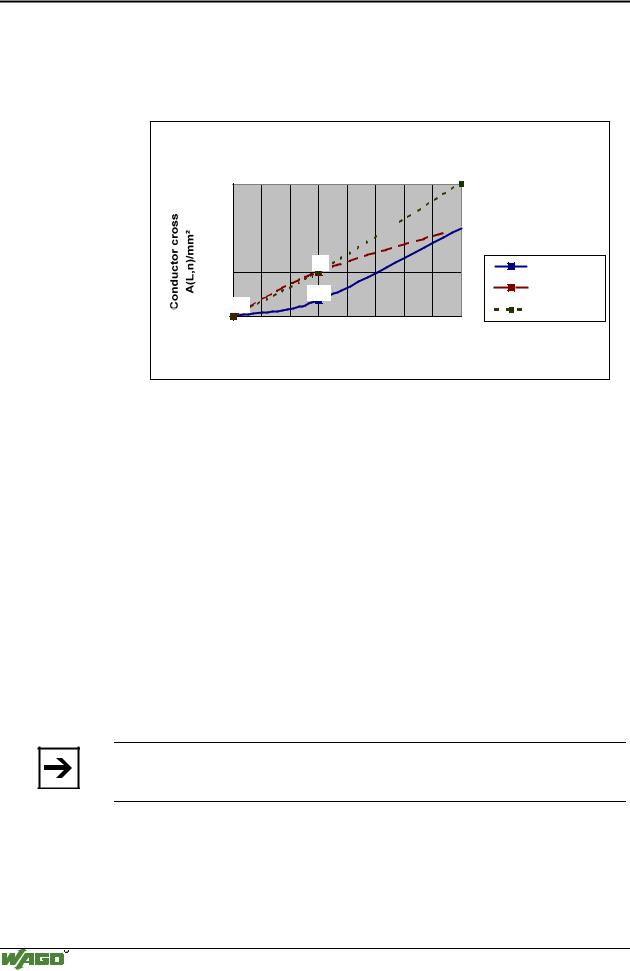
The conductor cross section depends on the conductor length and has to be selected according to the number of nodes connected.

1

1

0,75 0,75

0,5

0,5

32 nodes


0,34

64 nodes

0,25

100 nodes

0,25


100 150 200 250 300 350 400 450 500


Conductor length L/m


Fig. 5-1: Conductor cross section depending on the conductor length and the number of nodes

5.2.2 Cabling

The connection of a WAGO fieldbus node to the CANopen bus cable is made by the appropriate supplied plug (5-pole plug MCS or 9-pole plug D-SUB).

For cabling with a shielded copper cable (3x0.25 mm²), the plug is assigned with the CAN_High, CAN_Low and CAN_GND connections.

CAN_High and CAN_Low are two physically different bus levels. CAN_GND is the common reference potential.

The conductor shield of the cable can be routed on the connection drain, which is terminated with 1 Mas against the ground or PE (carrier rail contact). A low ohmic connection of the shield to the PE can only be made externally (i.e. by means of a supply module). The aim is for a central PE contact for the entire CANopen bus conductor screening.

Note

WAGO offers the screen connection system (series 790) for an optimum connection between fieldbus cable screening and functional earth.

Each CAN node forms the differential voltage UDiff with: UDiff = UCAN_High - UCAN_Low. from the bus levels CAN_High and CAN_Low.

The different signal transmission offers the advantage of being immune to common mode interference and ground offset between nodes.

WAGO-I/O-SYSTEM 750

CANopen

Источник: https://studfile.net/preview/16369781/