108• Fieldbus Controller 750-837, /02x-000, 750-838, /02x-000 LED Display
Fault code 5: "Internal bus initialization fault"
Fault argument |
Fault description |
Trouble shooting |
n* |
Error in register communication |
Turn off the power supply of the |
|
during internal bus initialization |
node and replace nth process data |
|
|
module and turn the power supply |
|
|
on again |
Fault code 6: " Project engineering node configuration fault " |
|
Fault argument |
|
|
Fault description |
|
|
Trouble shooting |
|
|
n |
|
|
Wrongly configured I/O module |
|
|
Check the Spacer module mapping |
|
|
|
|
|
in the Spacer module mapping |
|
|
|
|
|
|
|
|
|
|
|
|
|
Fault code 9: " CPU exception fault " |
|
|
|
|
|
Fault argument |
|
|
Fault description |
|
|
Trouble shooting |
|
|
1 |
|
|
Invalid program instruction |
|
|
Program sequence malfunction. |
|
|
|
|
|
|
|
|
Please contact the WAGO I/O |
|
|
2 |
|
|
Stack overflow |
|
|
|
|
|
|
|
|
support |
|
3Stack underflow
4Invalid event (NMI)
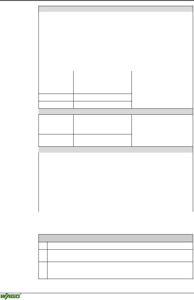
Fault code 10: "PLC program fault "
Fault argument |
Fault description |
Trouble shooting |
1 |
Invalid offset address for digital |
Correct the offset address in the |
|
inputs |
appropriate function block. |
2Invalid offset address for digital outputs
Fault code 11: "Gateway-/Mailbox I/O module fault"
Fault argument |
Fault description |
Trouble shooting |
1 |
Maximum number of Gateway |
Turn off the power supply of the |
|
modules exceeded |
node, reduce number of Gateway |
|
|
modules and turn the power supply |
|
|
on again. |
|
|
|
2 |
Maximum size of Mailbox ex- |
Reduce the Mailbox size. |
|
ceeded |
|
|
|
|
3 |
Maximum size of process image |
Reduce the data width of the |
|
exceeded due to the put Gateway |
Gateway modules. |
|
modules |
|
|
|
|
* The number of blink pulses (n) indicates the position of the I/O module. I/O modules without data are not counted (e.g. supply module without diagnosis)
Example: The 13th I/O module has been removed.
1.The I/O-LED starts the fault display with the first blink sequence (approx. 10 Hz).
2.The second blink phase (approx. 1 Hz) follows the first pause. The I/O-LED blinks four times and thus signals the fault code 4 (internal bus data fault).
3.The third blink sequence follows the second pause. The I/O-LED blinks twelve times. The fault argument 12 means that the internal bus is interrupted after the 12th I/O module.
WAGO-I/O-SYSTEM 750
CANopen