Материал: m083700e

Внимание! Если размещение файла нарушает Ваши авторские права, то обязательно сообщите нам

Fieldbus Controller 750-837, /02x-000, 750-838, /02x-000 • 101

LED Display

3.1.8 LED Display

The controller possesses several LED’s for on site display of the coupler operating status or the complete node.

CANopen

01 02


CANopen

01 02


STOP

A

C

STOP

A

A


C


C

RUN

B

A

RUN

B

B

D

D

TX

24V 0V


TX

24V 0V


OVERFLOW


OVERFLOW


RX


RX


I/O


I/O


USR


USR


Fig. 3-18: Display elements


g083702x

Here is a description of the two groups of LEDs.

The first group = fieldbus contains the solid colored LEDs with the notation STOP (red), RUN (green), Tx-Overflow (red) and Rx-Overflow (red) displays the operating status of the communication via CAN.

The second group = module bus consists of the three-color I/O LED (red/green/orange). The module bus status and the software exception codes are displayed by this LED.

The three-color USR-LED can be accessed by a user program in the programmable fieldbus controller.

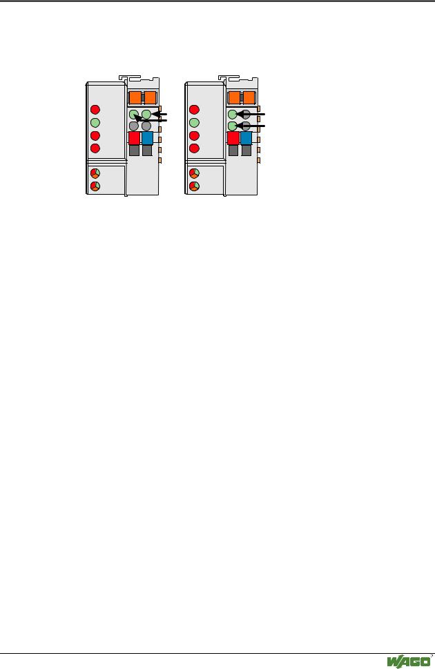
LEDs located on the right-hand side in the coupler feed section show the status of the supply voltage.

WAGO-I/O-SYSTEM 750

CANopen

102• Fieldbus Controller 750-837, /02x-000, 750-838, /02x-000 LED Display

3.1.8.1 Fieldbus status

The upper four LED´s (STOP, RUN, Txund Rx-Overflow) signal the operating conditions of the CAN communication.

STOP

RUN

TXOVERF

RXOVERF

Meaning

Remedy

OFF

OFF

OFF

OFF

No function or self-

check supply


test

(24V and 0V),


wait for self-test

OFF

SLOW

X

X

Module is in the


FLASHING


state PRE-


OPERATIONAL


OFF

ON

X

X

Module is in the


state


OPERATIONAL


ON

OFF

X

X

Module is in the

Check in the event


STOP state or fatal

of a fieldbus inde-


fieldbus independent

pendent error, reset


error (i.e. a module

the node, check the


was removed),

same in the event of


incorrect configura-

a configuration error


tion


X

X

X

ON

CAN receiver buffer

Increase the time


is full. Data loss is

span between 2


likely.

protocols.

X

X

ON

X

CAN transmitter

Check the data sizes


buffer is full. Data

of the bus system.


loss is likely.

Increase the transmit


priority of the


Module.

X

X

FAST

FAST

CAN Controller

Check baud rate and


FLASHING

FLASHING

exceeded the Warn-

bus connection,


in turns with

in turns with

ing Level, to many

install min. 2 mod-


RXOVERF

TXOVERF

error messages

ules in the network.

OFF

FAST

X

X

Module is in the

Change into the state


FLASHING


state PRE-

OPERATIONAL


OPERATIONAL,

and restart


Sync/Guard Mes-

Sync/Guard mes-


sage/Heartbeat failed

sage/Heartbeat

FAST

FAST

X

X

Module is in the

Restart Sync/Guard

FLASHING

FLASHING


state

message/Heartbeat


OPERATIONAL,


Sync/Guard Mes-


sage/Heartbeat failed


FAST

OFF

X

X

Module is in the

Change into the state

FLASHING


state STOP,

OPERATIONAL


Sync/Guard Mes-

and restart


sage/Heartbeat failed

Sync/Guard mes-


sage/Heartbeat

WAGO-I/O-SYSTEM 750

CANopen

Fieldbus Controller 750-837, /02x-000, 750-838, /02x-000 • 103

LED Display

3.1.8.2 Node Status – Blink code from the 'I/O' LED

LED

Color

Meaning

IO

red /green

The 'I/O' LED indicates the node operation and signals faults occur-


/orange

ring.


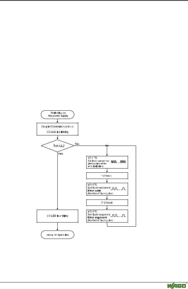
The coupler starts after switching on the supply voltage. The "I/O" LED flashes red. Following an error free start up the "I/O" LED changes to green steady light.

In the case of a fault the "I/O" LED continues blinking red. The fault is cyclically displayed with the blink code.

Detailed fault messages are displayed with the aid of a blink code. A fault is cyclically displayed with up to 3 blink sequences.

The first blink sequence (approx. 10 Hz) starts the fault display.

The second blink sequence (approx. 1 Hz) following a pause. The number of blink pulses indicates the fault code.

The third blink sequence (approx. 1 Hz) follows after a further pause. The number of blink pulses indicates the fault argument.

Fig. 3-19: Signalling of the LED for indication of the node status

g012111e

After clearing a fault, restart the coupler by cycling the power.

WAGO-I/O-SYSTEM 750

CANopen

104• Fieldbus Controller 750-837, /02x-000, 750-838, /02x-000 LED Display

I/O

Meaning

green

Data cycle on the internal bus


off

No data cycle on the internal bus


red

Coupler hardware defective


red flashing

a) During startup of fieldbus controller: Internal bus being initialized,


b) After startup of fieldbus controller: General internal bus fault


red cyclic flash-

Fault message in case of an internal bus reset and an internal error.

ing

This fault message is indicated by an error code of three consecutive


flashing sequences. There is a short pause between each sequential


flash.


Fault message of the 'I/O' LED

1st blink sequence: Start of the Fault message

2nd blink sequence: Fault code

3rd blink sequence: Fault argument

Fault code 1: " Hardware and configuration fault "

Fault argument

Fault description

Trouble shooting

-

Invalid fieldbus cou-

Turn off the power supply of the


pler/controller parameter check-

node, reduce number of I/O mod-


sum

ules and turn the power supply on


again

1

Overflow of the internal buffer

Turn off the power supply of the


memory for the inline code

node, reduce number of I/O mod-


ules and turn the power supply on


again. If the error still exists, ex-


change the bus coupler.

2

I/O module(s) with unsupported

Detect faulty I/O module as fol-


data type

lows: turn off the power supply.


Place the end module in the middle


of the fieldbus node. Turn the


power supply on again.


– If the LED is still blinking, turn


off the power supply and place the


end module in the middle of the


first half of the node (towards the


coupler).


– If the LED doesn’t blink, turn off


the power supply and place the end


module in the middle of the second


half of the node (away from the


coupler).


Turn the power supply on again.


Repeat this procedure until the


faulty I/O module is detected.


Replace the faulty I/O module.


Ask about a firmware update for


the fieldbus coupler.

WAGO-I/O-SYSTEM 750

CANopen

Fieldbus Controller 750-837, /02x-000, 750-838, /02x-000 • 105


LED Display


3

Module type of the flash pro-

Turn off the power supply of the


gram memory could not be de-

node, exchange fieldbus coupler


termined / is incorrect

and turn the power supply on


again.


4

Error occurred when writing to

Turn off the power supply of the


flash memory

node, exchange fieldbus coupler


and turn the power supply on


again.


5

Error occurred when erasing

Turn off the power supply of the


flash sector

node, exchange fieldbus coupler


and turn the power supply on


again.


6

Changed I/O module configura-

Restart the fieldbus coupler by


tion determined after

turning the power supply off and


AUTORESET

on again.


7

Error occurred when writing to

Turn off the power supply of the


serial EEPROM

node, exchange fieldbus coupler


and turn the power supply on


again.


8

Firmware does not run on exist-

Turn off the power supply of the


ing hardware

node, exchange fieldbus coupler


and turn the power supply on


again.


9

Invalid checksum in the serial

Turn off the power supply of the


EEPROM

node, exchange fieldbus coupler


and turn the power supply on


again.


10

Initialization of serial EEPROM

Turn off the power supply of the


failed

node, exchange fieldbus coupler


and turn the power supply on


again.


11

Error occurred with read access

Turn off the power supply of the


to serial EEPROM

node, exchange fieldbus coupler


and turn the power supply on


again.


12

Time limit exceeded for access-

Turn off the power supply of the


ing the serial EEPROM

node, exchange fieldbus coupler


and turn the power supply on


again.


14

Maximum number of Gateway or

Turn off the power supply of the


Mailbox I/O modules exceeded

node, reduce number of Gateway


or Mailbox I/O modules and turn


the power supply on again.


Fault code 2: -not used-


Fault argument

Fault description

Trouble shooting


-

not used

-


WAGO-I/O-SYSTEM 750

CANopen

Источник: https://studfile.net/preview/16369781/