Материал: m083700e
6 • Important Comments
Symbols
1.2 Symbols
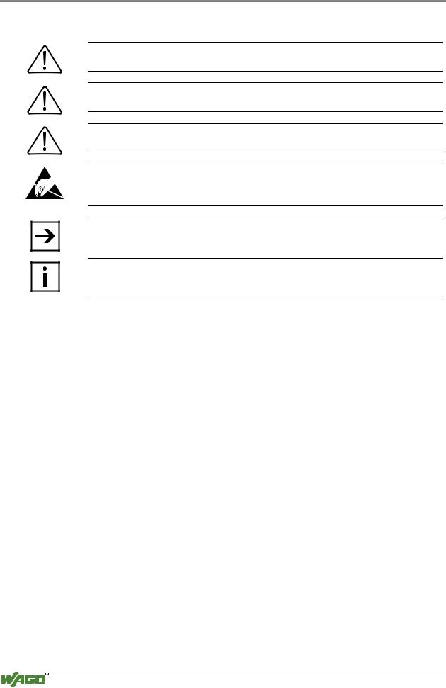
Danger
Always abide by this information to protect persons from injury.
Warning
Always abide by this information to prevent damage to the device.
Attention
Marginal conditions must always be observed to ensure smooth operation.
ESD (Electrostatic Discharge)
Warning of damage to the components by electrostatic discharge. Observe the precautionary measure for handling components at risk.
Note
Routines or advice for efficient use of the device and software optimization.
More information
References on additional literature, manuals, data sheets and INTERNET pages
1.3 Font Conventions
Italic
Italic
\
END
< >
Courier
Names of path and files are marked italic i.e.: C:\programs\WAGO-IO-CHECK
Menu items are marked as bold italic i.e.: Save
A backslash between two names marks a sequence of menu items
i.e.: File\New
Press buttons are marked as bold with small capitals i.e.: ENTER
Keys are marked bold within angle brackets i.e.: <F5>
Program code is printed with the font Courier. i.e.: END_VAR
1.4 Number Notation
Number Code |
Example |
Note |
Decimal |
100 |
normal notation |
Hexadecimal |
0x64 |
C notation |
Binary |
'100' |
Within ', |
|
'0110.0100' |
Nibble separated with dots |
WAGO-I/O-SYSTEM 750
CANopen
Important Comments |
• 7 |
Safety Notes |
|
|
|
1.5 Safety Notes
Attention
Switch off the system prior to working on bus modules!
In the event of deformed contacts, the module in question is to be replaced, as its functionality can no longer be ensured on a long-term basis.
The components are not resistant against materials having seeping and insulating properties. Belonging to this group of materials is: e.g. aerosols, silicones, triglycerides (found in some hand creams).
If it cannot be ruled out that these materials appear in the component environment, then additional measures are to be taken:
-installation of the components into an appropriate enclosure
-handling of the components only with clean tools and materials.
Attention
Cleaning of soiled contacts may only be done with ethyl alcohol and leather cloths. Thereby, the ESD information is to be regarded.
Do not use any contact spray. The spray may impair the functioning of the contact area.
The WAGO-I/O-SYSTEM 750 and its components are an open system. It must only be assembled in housings, cabinets or in electrical operation rooms. Access must only be given via a key or tool to authorized qualified personnel.
The relevant valid and applicable standards and guidelines concerning the installation of switch boxes are to be observed.
ESD (Electrostatic Discharge)
The modules are equipped with electronic components that may be destroyed by electrostatic discharge. When handling the modules, ensure that the environment (persons, workplace and packing) is well grounded. Avoid touching conductive components, e.g. gold contacts.
WAGO-I/O-SYSTEM 750
CANopen
8 • The WAGO-I/O-SYSTEM 750
System Description
2 The WAGO-I/O-SYSTEM 750
2.1 System Description
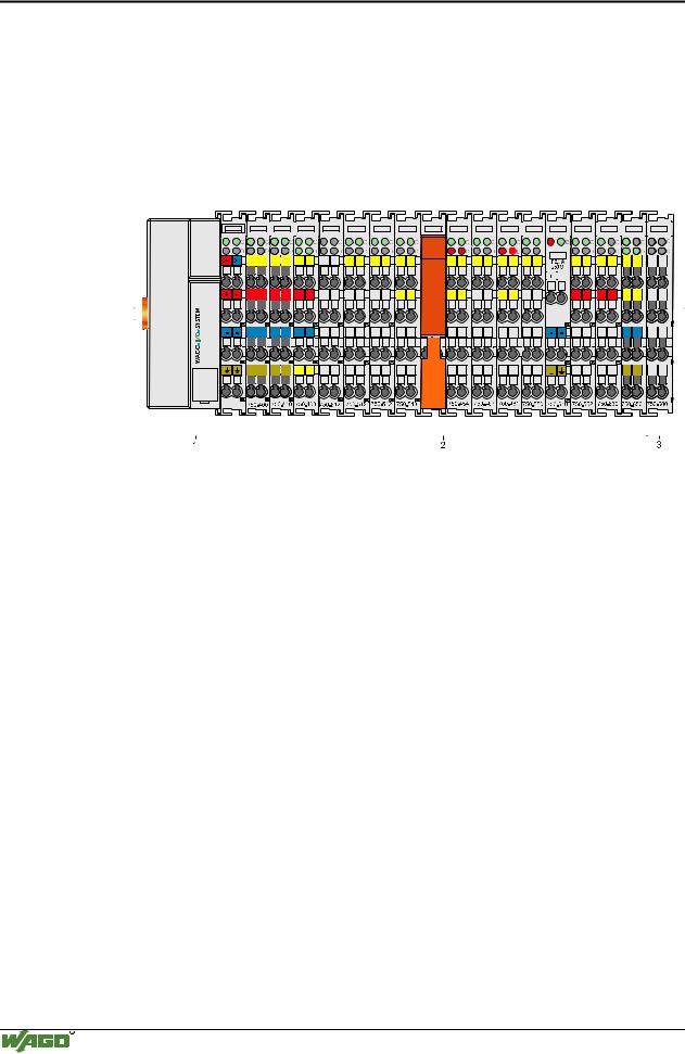
The WAGO-I/O-SYSTEM 750 is a modular, fieldbus independent I/O system. It is comprised of a fieldbus coupler/controller (1) and up to 64 connected fieldbus modules (2) for any type of signal. Together, these make up the fieldbus node. The end module (3) completes the node.
|
|
|
|
|
|
|
|
|
|
|
|
|
|
|
|
|
|
|
|
|
|
|
|
|
|
|
|
|
|
|
|
|
|
|
|
|
|
|
|
|
|
|
|
|
|
|
|
|
|
|
|
|
|
|
|
|
|
|
|
|
|
|
|
|
|
|
|
|
|
|
|
|
|
|
|
|
|
|
|
|
|
|
|
|
|
|
|
|
|
|
|
|
|
|
|
|
|
|
|
|
|
|
|
|
|
|
|
|
|
|
|
|
|
|
|
|
|
|
|
|
|
|
|
|
|
|
|
|
|
|
|
|
|
|
|
|
|
|
|
|
|
|
|
|
|
|
|
|
|
|
|
|
|
|
|
|
|
|
|
|
|
|
|
|
|
|
|
|
|
|
|
|
|
|
|
|
|
|
|
|
|
|
|
|
|
|
|
|
|
|
|
|
|
|
|
|
|
|
|
|
|
|
|
|
|
|
|
|
|
|
|
|
|
|
|
|
|
|
|
|
|
|
|
|
|
|
|
|
|
|
|
|
|
|
|
|
|
|
|
|
|
|
|
|
|
|
|
|
|
|
|
|
|
|
|
|
|
|
|
|
|
|
|
|
|
|
|
|
|
|
|
|
|
|
|
|
|
|
|
|
|
|
|
|
|
|
|
|
|
|
|
|
|
|
|
|
|
|
|
|
|
|
|
|
|
|
|
|
|
|
|
|
|
|
|
|
|
|
|
|
|
|
|
|
|
|
|
|
|
|
|
|
|
|
|
|
|
|
|
|
|
|
|
|
|
|
|
|
|
|
|
|
|
|
|
|
|
|
|
|
|
|
|
|
|
|
|
|
|
|
|
|
|
|
|
|
|
|
|
|
|
|
|
|
|
|
|
|
|
|
|
|
|
|
|
|
|
|
|
|
|
|
|
|
|
|
|
|
|
|
|
|
|
|
|
|
|
|
|
|
|
|
|
|
|
|
|
|
|
|
|
|
|
|
|
|
|
|
|
|
|
|
|
|
|
|
|
|
|
|
|
|
|
|
|
|
|
|
|
|
|
|
|
|
|
|
|
|
|
|
|
|
|
|
|
|
|
|
|
|
|
|
|
|
|
|
|
|
|
|
|
|
|
|
|
|
|
|
|
|
|
|
|
|
|
|
|
|
|
|
|
|
|
|
|
|
|
|
|
|
|
|
|
|
|
|
|
|
|
|
|
|
|
|
|
|
|
|
|
|
|
|
|
|
|
|
|
|
|
|
|
|
|
|
|
|
|
|
|
|
|
|
|
|
|
|
|
|
|
|
|
|
|
|
|
|
|
|
|
|
|
|
|
|
|
|
|
|
|
|
|
|
|
|
|
|
|
|
|
|
|
|
|
|
|
|
|
|
|
|
|
|
|
|
|
|
|
|
|
|
|
|
|
|
|
|
|
|
|
|
|
|
|
|
|
|
|
|
|
|
|
|
|
|
|
|
|
|
|
|
|
|
|
|
|
|
|
|
|
|
|
|
|
|
|
|
|
|
|
|
|
|
|
|
|
|
|
|
|
|
|
|
|
|
|
|
|
|
|
|
|
|
|
|
|
|
|
|
|
|
|
|
|
|
|
|
|
|
|
|
|
|
|
|
|
|
|
|
|
|
|
|
|
|
|
|
|
|
|
|
|
|
|
|
|
|
|
|
|
|
|
|
|
|
|
|
|
|
|
|
|
|
|
|
|
|
|
|
|
|
|
|
|
|
|
|
|
|
|
|
|
|
|
|
|
|
|
|
|
|
|
|
|
|
|
|
|
|
|
|
|
|
|
|
|
|
|
|
|
|
|
|
|
|
|
|
|
|
|
|
|
|
|
|
|
|
|
|
|
|
|
|
|
|
|
|
|
|
|
|
|
|
|
|
|
|
|
|
|
|
|
|
|
|
|
|
|
|
|
|
|
|
|
|
|
|
|
|
|
|
|
|
|
|
|
|
|
|
|
|
|
|
|
|
|
|
|
|
|
|
|
|
|
|
|
|
|
|
|
|
|
|
|
|
|
|
|
|
|
|
|
|
|
|
|
|
|
|
|
|
|
|
|
|
|
|
|
|
|
|
|
|
|
|
|
|
|
|
|
|
|
|
|
|
|
|
|
|
|
|
|
|
|
|
|
|
|
|
|
|
|
|
|
|
|
|
|
|
|
|
|
|
|
|
|
|
|
|
|
|
|
|
|
|
|
|
|
|
|
|
|
|
|
|
|
|
|
|
|
|
|
|
|
|
|
|
|
|
|
|
|
|
|
|
|
|
|
|
|
|
|
|
|
|
|
|
|
|
|
|
|
|
|
|
|
|
|
|
|
|
|
|
|
|
|
|
|
|
|
|
|
|
|
|
|
|
|
|
|
|
|
|
|
|
|
|
|
|
|
|
|
|
|
|
|
|
|
|
|
|
|
|
|
|
|
|
|
|
|
|
|
|
|
|
|
|
|
|
|
|
|
|
|
|
|
|
|
|
|
|
|
|
|
|
|
|
|
|
|
|
|
|
|
|
|
|
|
|
|
|
|
|
|
|
|
|
|
|
|
|
|
|
|
|
|
|
|
|
|
|
|
|
|
|
|
|
|
|
|
|
|
|
|
|
|
|
|
|
|
|
|
|
|
|
|
|
|
|
|
|
|
|
|
|
|
|
|
|
|
|
|
|
|
|
|
|
|
|
|
|
|
|
|
|
|
|
|
|
|
|
|
|
|
|
|
|
|
|
|
|
|
|
|
|
|
|
|
|
|
|
|
|
|
|
|
|
|
|
|
|
|
|
|
|
|
|
|
|
|
|
|
|
|
|
|
|
|
|
|
|
|
|
|
|
|
|
|
|
|
|
|
|
|
|
|
|
|
|
|
|
|
|
|
|
|
|
|
|
|
|
|
|
|
|
|
|
|
|
|
|
|
|
|
|
|
|
|
|
|
|
|
|
|
|
|
|
|
|
|
|
|
|
|
|
|
|
|
|
|
|
|
|
|
|
|
|
|
|
|
|
|
|
|
|
|
|
|
|
|
|
|
|
|
|
|
|
|
|
|
|
|
|
|
|
|
|
|
|
|
|
|
|
|
|
|
|
|
|
|
|
|
|
|
|
|
|
|
|
|
|
|
|
|
|
|
|
|
|
|
|
|
|
|
|
|
|
|
|
|
|
|
|
|
|
|
|
|
|
|
|
|
|
|
|
|
|
|
|
|
|
|
|
|
|
|
|
|
|
|
|
|
|
|
|
|
|
|
|
|
|
|
|
|
|
|
|
|
|
|
|
|
|
|
|
|
|
|
|
|
|
|
|
|
|
|
|
|
|
|
|
|
|
|
|
|
|
|
|
|
|
|
|
|
|
|
|
|
|
|
|
|
|
|
|
|
|
|
|
|
|
|
|
|
|
|
|
|
|
|
|
|
|
|
|
|
|
|
|
|
|
|
|
|
|
|
|
|
|
|
|
|
|
|
|
|
|
|
|
|
|
|
|
|
|
|
|
|
|
|
|
|
|
|
|
|
|
|
|
|
|
|
|
|
|
|
|
|
|
|
|
|
|
|
|
|
|
|
|
|
|
|
|
|
|
|
|
|
|
|
|
|
|
|
|
|
|
|
|
|
|
|
|
|
|
|
|
|
|
|
|
|
|
|
|
|
|
|
|
|
|
|
|
|
|
|
|
|
|
|
|
|
|
|
|
|
|
|
|
|
|
|
|
|
|
|
|
|
|
|
|
|
|
|
|
|
|
|
|
|
|
|
|
|
|
|
|
|
|
|
|
|
|
|
|
|
|
|
|
|
Fig. 2-1: Fieldbus node |
|
|
|
|
|
|
|
|
|
|
g0xxx00x |
||||||||||||||||||||||||||||||||||||||||||||||||||||||||||
Couplers / controllers for fieldbus systems such as PROFIBUS, INTERBUS, ETHERNET TCP/IP, CAN (CANopen, DeviceNet, CAL), MODBUS, LON and others are available.
The coupler / controller contains the fieldbus interface, electronics and a power supply terminal. The fieldbus interface forms the physical interface to the relevant fieldbus. The electronics process the data of the bus modules and make it available for the fieldbus communication. The 24 V system supply and the 24 V field supply are fed in via the integrated power supply terminal.
The fieldbus coupler communicates via the relevant fieldbus. The programmable fieldbus controller (PFC) enables the implementation of additional PLC functions. Programming is done with the WAGO-I/O-PRO 32 in accordance with IEC 61131-3.
Bus modules for diverse digital and analog I/O functions as well as special functions can be connected to the coupler / controller. The communication between the coupler/controller and the bus modules is carried out via an internal bus.
The WAGO-I/O-SYSTEM 750 has a clear port level with LEDs for status indication, insertable mini WSB markers and pullout group marker carriers. The 3-wire technology supplemented by a ground wire connection allows for direct sensor/actuator wiring.
WAGO-I/O-SYSTEM 750
CANopen

|
|
The WAGO-I/O-SYSTEM 750 |
• 9 |
|
|
|
Technical Data |
|
|
|
|
|
|
|
2.2 Technical Data |
|
|
|
|
|
|
|
|
|
|
Mechanic |
|
|
|
|
Material |
Polycarbonate, Polyamide 6.6 |
|
|
|
|
|
|
|
|
Dimensions |
|
|
|
|
- Coupler / Controller |
- 51 mm x 65* mm x 100 mm |
|
|
|
- I/O module, single |
- 12 mm x 64* mm x 100 mm |
|
|
|
- I/O module, double |
- 24 mm x 64* mm x 100 mm |
|
|
|
|
* from upper edge of DIN 35 rail |
|
|
|
|
|
|
|
|
Installation |
on DIN 35 with interlock |
|
|
|
|
|
|
|
|
modular by |
double featherkey-dovetail |
|
|
|
|
|
|
|
|
Mounting position |
any position |
|
|
|
|
|
|
|
|
Length of entire node |
≤ 831 mm |
|
|
|
|
|
|
|
|
Marking |
marking label type 247 and 248 |
|
|
|
|
paper marking label 8 x 47 mm |
|
|
|
|
|
|
|
|
Wire range |
|
|
|
|
Wire range |
CAGE CLAMP® Connection |
|
|
|
|
0,08 mm² ... 2.5 mm² |
|
|
|
|
AWG 28-14 |
|
|
|
|
8 – 9 mm Stripped length |
|
|
|
|
|
|
|
|
Contacts |
|
|
|
|
Power jumpers contacts |
blade/spring contact |
|
|
|
|
self-cleaning |
|
|
|
|
|
|
|
|
Current via power contactsmax |
10 A |
|
|
|
Voltage drop at Imax |
< 1 V/64 modules |
|
|
|
Data contacts |
slide contact, hard gold plated |
|
|
|
|
1,5µm, self-cleaning |
|
|
|
|
|
|
|
|
Climatic environmental conditions |
|
|
|
|
Operating temperature |
0 °C ... 55 °C |
|
|
|
|
|
|
|
|
Storage temperature |
-20 °C ... +85 °C |
|
|
|
|
|
|
|
|
Relative humidity |
5% to 95 % without condensation |
|
|
|
|
|
|
|
|
Resistance to harmful substances |
acc. To IEC 60068-2-42 and IEC 60068-2-43 |
|
|
|
|
|
|
|
|
Maximum pollutant concentration at |
SO2 ≤ 25 ppm |
|
|
|
relative humidity < 75% |
H2S ≤ 10 ppm |
|
|
|
Special conditions |
Ensure that additional measures for components are |
|
|
|
|
taken, which are used in an environment involving: |
|
|
|
|
– dust, caustic vapors or gasses |
|
|
|
|
– ionization radiation. |
|
|
|
|
|
|
|
WAGO-I/O-SYSTEM 750
CANopen
10 • The WAGO-I/O-SYSTEM 750
Technical Data
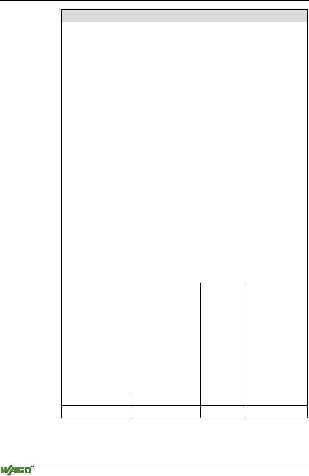
Mechanical strength
Vibration resistance |
|
|
acc. to IEC 60068-2-6 |
|
|
||||
|
|
|
|
Comment to the vibration restistance: |
|||||
|
|
|
|
a) Type of oscillation: |
|
|
|||
|
|
|
|
sweep with a rate of change of 1 octave per minute |
|||||
|
|
|
|
10 Hz ≤ f < 57 Hz, const. Amplitude 0,075 mm |
|||||
|
|
|
|
57 Hz ≤ f < 150 Hz, const. Acceleration 1 g |
|||||
|
|
|
|
b) Period of oscillation: |
|
|
|||
|
|
|
|
10 sweep per axis in each of the 3 vertical axes |
|||||
|
|
|
|
|
|
|
|
|
|
Shock resistance |
|
|
acc. to IEC 60068-2-27 |
|
|
||||
|
|
|
|
Comment to the shock restistance: |
|||||
|
|
|
|
a) Type of impulse: half sinusoidal |
|||||
|
|
|
|
b) Intensity of impulse: |
|
|
|||
|
|
|
|
15 g peak value, 11 ms maintenance time |
|||||
|
|
|
|
c) Route of impulse: |
|
|
|||
|
|
|
|
3 impulses in each pos. And neg. direction of the |
|||||
|
|
|
|
3 vertical axes of the test object, this means |
|||||
|
|
|
|
18 impulses in all |
|
|
|||
|
|
|
|
|
|
|
|
|
|
Free fall |
|
|
acc. to IEC 60068-2-32 |
|
|
||||
|
|
|
|
≤ 1m |
(module in original packing) |
||||
|
|
|
|
|
|
|
|
|
|
Safe electrical isolation |
|
|
|
|
|
|
|
|
|
Air and creepage distance |
|
|
acc. to IEC 60664-1 |
|
|
||||
|
|
|
|
|
|
|
|
|
|
Degree of pollution |
|
|
2 |
|
|
|
|
|
|
acc. To IEC 61131-2 |
|
|
|
|
|
|
|
|
|
|
|
|
|
|
|
|
|
|
|
Degree of protection |
|
|
|
|
|
|
|
|
|
Degree of protection |
|
|
IP 20 |
|
|
|
|
|
|
|
|
|
|
|
|
|
|
|
|
Electromagnetic compatibility* |
|
|
|
|
|
|
|||
Directive |
|
Test values |
|
|
|
Strength class |
|
Evaluation criteria |
|
Immunity to interference acc. to EN 50082-2 (96) |
|
|
|||||||
EN 61000-4-2 |
|
4kV/8kV |
|
(2/4) |
|
B |
|||
|
|
|
|
|
|
||||
EN 61000-4-3 |
|
10V/m 80% AM |
(3) |
|
A |
||||
|
|
|
|
|
|
|
|||
EN 61000-4-4 |
|
2kV |
|
(3/4) |
|
B |
|||
|
|
|
|
|
|
||||
EN 61000-4-6 |
|
10V/m 80% AM |
(3) |
|
A |
||||
|
|
|
|
|
|
|
|
||
Emission of interference acc. to |
|
|
|
Measuring |
|
Class |
|||
EN 50081-2 (94) |
|
|
|
|
|
distance |
|
|
|
EN 55011 |
|
30 dBµV/m |
|
|
|
(30m) |
|
A |
|
|
|
|
|
|
|
|
|
|
|
|
|
37 dBµV/m |
|
|
|
|
|
|
|
|
|
|
|
|
|
|
|
||
Emission of interference acc. to |
|
|
|
Measuring |
|
Class |
|||
EN 50081-1 (93) |
|
|
|
|
|
distance |
|
|
|
EN 55022 |
30 dBµV/m |
|
|
|
(10m) |
|
B |
||
37dBµV/m
*Exception: 750-630, 750-631
WAGO-I/O-SYSTEM 750
CANopen