Материал: m083700e
|
|
|
|
The WAGO-I/O-SYSTEM 750 • 11 |
||
|
|
|
|
|
Technical Data |
|
|
|
|
|
|
|
|
|
|
|
|
|
|
|
|
Range of applica- |
Required specification |
|
Required specification |
|
|
|
tion |
emission of interference |
|
immunity to interference |
|
|
|
Industrial areas |
EN 50081-2 |
: 1993 |
|
EN 50082-2 : 1996 |
|
|
Residential areas |
EN 50081-1 |
: 1993*) |
|
EN 50082-1 : 1992 |
|
|
|
|
|
|
|
|
*) The system meets the requirements on emission of interference in residential areas with the fieldbus coupler/controller for:
ETHERNET 750-342/-841/-842 LonWorks 750-319/-819 CANopen 750-337/-837 DeviceNet 750-306/-806
MODBUS 750-312/-314/ -315/ -316 750-812/-814/ -815/ -816
With a special permit, the system can also be implemented with other fieldbus couplers/controllers in residential areas (housing, commercial and business areas, small-scale enterprises). The special permit can be obtained from an authority or inspection office. In Germany, the Federal Office for Post and Telecommunications and its branch offices issues the permit.
It is possible to use other field bus couplers / controllers under certain boundary conditions. Please contact WAGO Kontakttechnik GmbH.
Maximum power dissipation of the components
Bus modules |
0.8 |
W / bus terminal (total power dissipation, sys- |
|
tem/field) |
|
|
|
|
Fieldbus coupler / controller |
2.0 |
W / coupler / controller |
|
|
|
Warning
The power dissipation of all installed components must not exceed the maximum conductible power of the housing (cabinet).
When dimensioning the housing, care is to be taken that even under high external temperatures, the temperature inside the housing does not exceed the permissible ambient temperature of 55 °C.
WAGO-I/O-SYSTEM 750
CANopen
12 • The WAGO-I/O-SYSTEM 750
Manufacturing Number
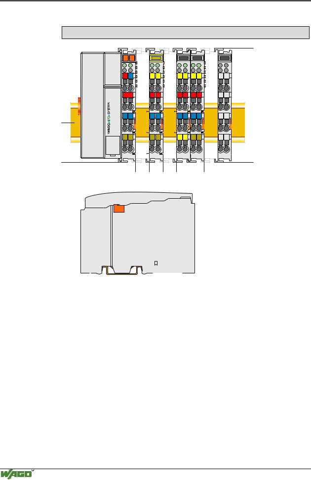
Dimensions
01 |
02 |
|
|
|
|
A |
|
A |
A |
A |
A |
|
C |
C |
C |
C |
C |
B |
|
B |
B |
B |
B |
|
D |
D |
D |
D |
D |
24V 0V
+ 
 +
+
100
- |
- |
35
51 |
12 |
24 |
65 |
64 |
|
|
|
|
|
|
|
|
|
|
|
|
|
|
|
|
|
|
|
|
|
|
|
|
|
|
|
|
|
|
|
|
|
|
|
|
|
|
|
|
|
|
Side view |
|
|
|
|
|
|
|
|
|
|
|
|
Dimensions in mm |
Fig. 2-2: Dimensions |
|
|
|
|
|
|
|
|
|
|
|
|
g01xx05e |
2.3 Manufacturing Number
The manufacturing number indicates the delivery status directly after production.
This number is part of the lateral marking on the component.
In addition, starting from calender week 43/2000 the manufacturing number is also printed on the cover of the configuration and programming interface of the fieldbus coupler or controller.
WAGO-I/O-SYSTEM 750
CANopen
The WAGO-I/O-SYSTEM 750 • 13
Component Update
24V DC AWG 28-14 55°C max ambient
LISTED 22ZA AND 22XM
0 1 0 3 0 0 0 2 0 3 - B 0 0 0 0 0 0
|
|
ITEM-NO.:750-333 |
||
GL |
Hansastr. 27 |
PROFIBUS DP 12 MBd /DPV1 |
||
|
|
|
||
|
D-32423 Minden |
|
|
|
2 |
|
- |
+ |
24 V |
7 |
|
0 V |
||
0 |
Power Supply |
|
Power Supply |
|
2 |
|
|||
Field |
|
|
Electronic |
|
7 NO DS SW HW FWL |
|
|
||
II 3 GD |
|
PATENTS PENDING |
||
|
|
|
|
|
|
DEMKO 02 ATEX132273 X |
|
|
|
|
EEx nA II T4 |
|
|
|
Manufacturing Number
|
0 1 0 3 0 0 0 2 0 3 |
- |
B 0 0 0 0 0 0 |
|
||
Calendar |
Year Software |
Hardware |
Firmware-loader Internal |
|||
week |
version |
version |
version |
Number |
||
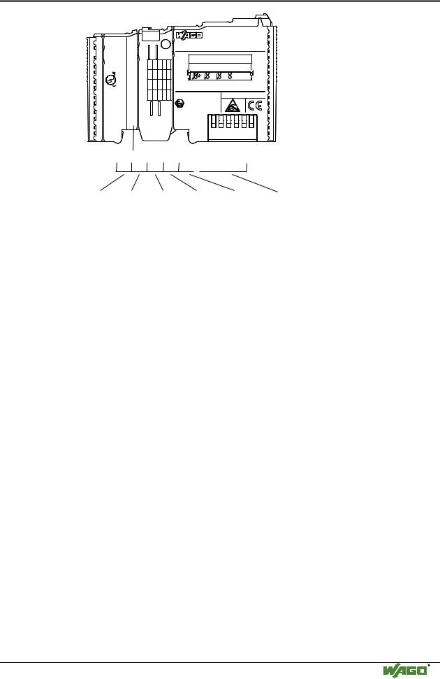
Fig. 2-3: Example: Manufacturing Number of a PROFIBUS fieldbus coupler 750-333
g01xx15e
The manufacturing number consists of the production week and year, the software version (if available), the hardware version of the component, the firmware loader (if available) and further internal information for
WAGO Kontakttechnik GmbH.
2.4 Component Update
For the case of an Update of one component, the lateral marking on each component contains a prepared matrix.
This matrix makes columns available for altogether three updates to the entry of the current update data, like production order number (NO; starting from calendar week 13/2004), update date (DS), software version (SW), hardware version (HW) and the firmware loader version (FWL, if available).
Update Matrix
Current Version data for: |
1. Update 2. Update |
3. Update |
|||
Production Order |
NO |
|
|
|
<- Only starting from Calen- |
Number |
|
|
|
|
dar week 13/2004 |
Datestamp |
DS |
|
|
|
|
Software index |
SW |
|
|
|
|
Hardware index |
HW |
|
|
|
|
Firmware loader |
FWL |
|
|
|
<- Only for coupler/controller |
index |
|
|
|
|
|
If the update of a component took place, the current version data are registered into the columns of the matrix.
Additionally with the update of a fieldbus coupler or controller also the cover of the configuration and programming interface of the coupler or controller is printed on with the current manufacturing and production order number.
The original manufacturing data on the housing of the component remain thereby.
WAGO-I/O-SYSTEM 750
CANopen
14 • The WAGO-I/O-SYSTEM 750
Storage, Assembly and Transport
2.5 Storage, Assembly and Transport
Wherever possible, the components are to be stored in their original packaging. Likewise, the original packaging provides optimal protection during transport.
When assembling or repacking the components, the contacts must not be soiled or damaged. The components must be stored and transported in appropriate containers/packaging. Thereby, the ESD information is to be regarded.
Statically shielded transport bags with metal coatings are to be used for the transport of open components for which soiling with amine, amide and silicone has been ruled out, e.g. 3M 1900E.
2.6 Mechanical Setup
2.6.1 Installation Position
Along with horizontal and vertical installation, all other installation positions are allowed.
Attention
In the case of vertical assembly, an end stop has to be mounted as an additional safeguard against slipping.
WAGO item 249-116 End stop for DIN 35 rail, 6 mm wide WAGO item 249-117 End stop for DIN 35 rail, 10 mm wide
2.6.2 Total Expansion
The maximum total expansion of a node is calculated as follows:
Quantity |
Width |
Components |
1 |
51 mm |
coupler / controller |
|
|
|
64 |
12 mm |
bus modules |
|
|
- inputs / outputs |
|
|
- power supply modules |
|
|
- etc. |
|
|
|
1 |
12 mm |
end module |
sum |
831 mm |
|
Warning
The maximal total expansion of a node must not exceed 831 mm
WAGO-I/O-SYSTEM 750
CANopen
The WAGO-I/O-SYSTEM 750 • 15
Mechanical Setup
2.6.3 Assembly onto Carrier Rail
2.6.3.1 Carrier rail properties
All system components can be snapped directly onto a carrier rail in accordance with the European standard EN 50022 (DIN 35).
Warning
WAGO supplies standardized carrier rails that are optimal for use with the I/O system. If other carrier rails are used, then a technical inspection and approval of the rail by WAGO Kontakttechnik GmbH should take place.
Carrier rails have different mechanical and electrical properties. For the optimal system setup on a carrier rail, certain guidelines must be observed:
•The material must be non-corrosive.
•Most components have a contact to the carrier rail to ground electromagnetic disturbances. In order to avoid corrosion, this tin-plated carrier rail contact must not form a galvanic cell with the material of the carrier rail which generates a differential voltage above 0.5 V (saline solution of 0.3% at 20°C) .
•The carrier rail must optimally support the EMC measures integrated into the system and the shielding of the bus module connections.
•A sufficiently stable carrier rail should be selected and, if necessary, several mounting points (every 20 cm) should be used in order to prevent bending and twisting (torsion).
•The geometry of the carrier rail must not be altered in order to secure the safe hold of the components. In particular, when shortening or mounting the carrier rail, it must not be crushed or bent.
•The base of the I/O components extends into the profile of the carrier rail. For carrier rails with a height of 7.5 mm, mounting points are to be riveted under the node in the carrier rail (slotted head captive screws or blind rivets).
WAGO-I/O-SYSTEM 750
CANopen