Материал: m083700e
96• Fieldbus Controller 750-837, /02x-000, 750-838, /02x-000 Starting up CANopen fieldbus nodes
1


 ON
ON
2

3 |
4


5


6


7


8


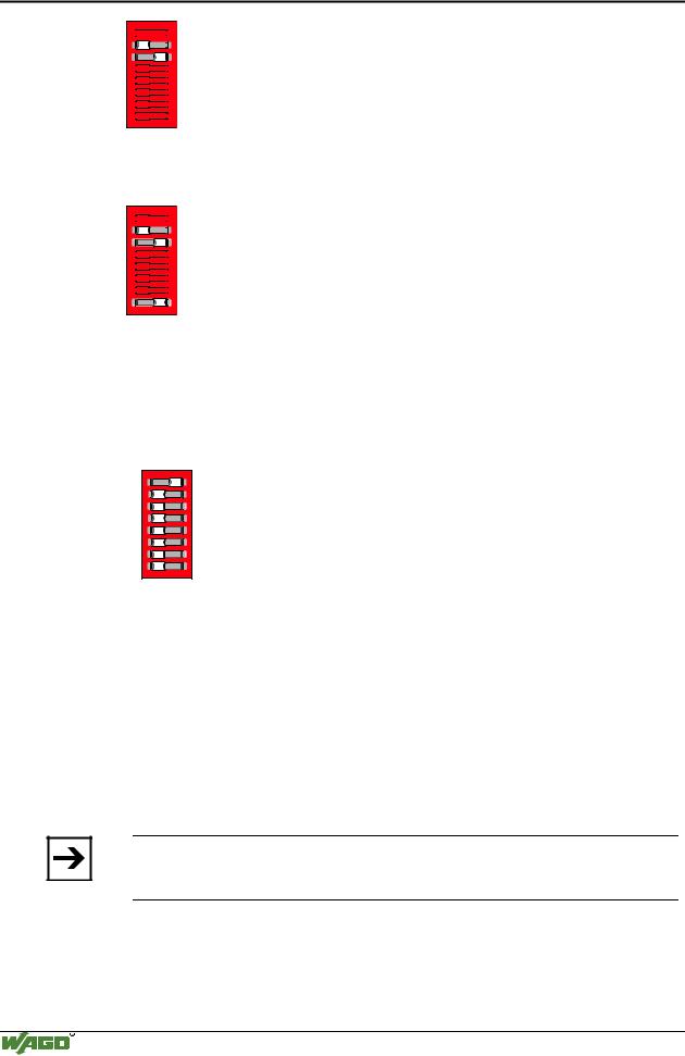
Fig. 3-15: Setting the Baud rate 125 kB |
g012443x |
To store the new setting, push the DIP switch 8 also to 'ON'.
Then switch the supply voltage of the controller off.
1


 ON
ON
2

3 |
4


5


6


7


8 |
Fig. 3-16: Store the Baud rate 125 kB |
g012441x |
3.1.7.3 Setting the module ID
The module ID is set with the supply voltage switched off. For this purpose, push all DIP switches temporarily to the “OFF” position. Then push the corresponding DIP switches for the desired module ID to “ON”, i.e. DIP switch 1 for the module ID 1.
1
2
3
4
5
6
7
8
1 2 |
ON |
3 |
|
4 |
|
5 |
|
6 |
|
7 |
|
8 |
|
ON
Fig. 3-17: Setting the module ID 1 |
g012440x |
Now as soon as the supply voltage is switched on, the controller is in the INITIALIZATION mode.
At the same time, the process image is created on the basis of the connected bus modules, and the object directory is initialized according to the default mapping, if no application specific configuration was stored.
Following an error free completion of the initialization phase, the controller automatically changes to the PRE-OPERATIONAL status.
In this status, the communication via SDOs is possible. You can now proceed with various settings via your CAN master software:
•You can set the coupler directly to the OPERATIONAL setting.
Note
Due to the fact that in the default setting the PDO transmission of the analog input data is switched off, the analog input data is not taken into account.
•You can turn off the deactivated transmission of analog input data or
•select an application specific mapping.
WAGO-I/O-SYSTEM 750
CANopen
Fieldbus Controller 750-837, /02x-000, 750-838, /02x-000 |
• 97 |
Starting up CANopen fieldbus nodes |
|
|
|
3.1.7.4 Changing to the OPERATIONAL status
The command Start_Remote_Node from the network management objects permits you to change the controller status from PRE-OPERATIONAL to OPERATIONAL. This establishes the communication readiness of the fieldbus node for PDOs (refer to chapter 5.3.3.1.1 "Start Remote Node").
Note
In the default setting, the PDO transmission of the analog input data is switched off. For this reason, this data is read out only once and not updated again. To allow this data to be used via PDOs, the analog input data in the PRE-OPERATIONAL status have to be turned on. In this manner, access via the SDOs is possible at any time.
If no further settings are performed, the controller is operational and communication possible in accordance with the default mapping (refer to chapter
5.3.4.1"Initialization").
3.1.7.5Turning on the analog input data
To prevent the CAN bus from being flooded with CAN messages, the transmission of analog input data via PDOs is deactivated in the default setting. This means that the object 0x6423 "Analoge Input Global Interrupt Enable" is assigned with the default value 'FALSE' (= '0') (refer to chapter 5.3.4.4.12
"Object 0x6423, Analog Input Global Interrupt Enable").
If the controller is in the PRE-OPERATIONAL status, you can enable the transmission in general by changing the object 0x6423 to the value TRUE (= '1').
Subsequently you can use the "Start Remote Node" command to change the controller PRE-OPERATIONAL status to the OPERATIONAL status. In this manner both communication via the PDOs and the transmission of analog input data are possible.
If no further settings are made, the controller is operational and communication can occur according to the default mapping (refer to chapter 5.3.4.1
"Initialization").
3.1.7.6 Application specific mapping
An alternative to the use of the default mapping is to define the data to be transmitted by PDOs in an application specific PDO mapping. For this purpose, the coupler has to be in the PRE-OPERATIONAL status.
Details of how to proceed with application specific mapping are explained as follows.
Example:
The 3rd and the 5th 2 byte analog input channel and the first 8 bit digital input group are to be read using the TxPDO 2. For transmission purposes, the CAN identifier 0x432 is to be used. Transmission must be synchronous with each 3rd SYNC object.
The default CAN IDs are used for the SDOs. The setting is made at node 8.
WAGO-I/O-SYSTEM 750
CANopen
98• Fieldbus Controller 750-837, /02x-000, 750-838, /02x-000 Starting up CANopen fieldbus nodes
xx... is not evaluated
1.First of all, deactivate the PDO mapping by zeroing the number of mapping objects in index 0x1A01, sub-index 0 (Transmit PDO Mapping Parameter).
Deactivating PDO mapping:
|
CAN ID |
Data |
Transmit |
608 |
0x2F 01 1A 00 00 xx xx xx |
Receive |
588 |
0x60 01 1A 00 xx xx xx xx |
|
|
|
2.Enter into the TxPDO mapping parameter structure (Index 0x1A01) the Index, Sub-Index and the Object length of the application object.
Max. 8 bytes of data can be assigned per PDO.
Writing into the mapping parameter structure:
Application object |
Index |
Sub-Index |
3. analog input channel |
0x6401 |
3 |
|
|
|
5. analog input channel |
0x6401 |
5 |
|
|
|
1. digital input group |
0x6000 |
1 |
|
|
|
3.The following structure must be reached in the mapping parameters of the 2nd TxPDO in order to acknowledge the task set:
TxPDO Mapping Parameter Structure, Index 0x1A01
|
|
|
|
|
Application object |
|
|
|
|
|
|
|
|
|
Sub-Index: |
|
|
Index: |
|
|
Sub-Index: |
|
|
Object length in Bit |
|
|
|
0 |
|
3 |
|
|
|
|
|
|
|
|
|
|
|
|
|
|
|
|
|
|
|
|
|
|
|
1 |
|
|
0x6401 |
|
3 |
|
|
0x10 |
|
|
|
|
|
|
|
|
|
|
|
|
|
|
|
|
|
2 |
|
|
0x6401 |
|
5 |
|
|
0x10 |
|
|
|
|
|
|
|
|
|
|
|
|
|
|
|
|
|
3 |
|
|
0x6000 |
|
1 |
|
|
0x08 |
|
|
|
|
|
|
|
|
|
|
|
|
|
|
|
Note
First of all, enter the mapping parameter sub-index 1 ... 8 in sub-index 0, followed by the number of valid sub-indexes.
These objects are stored with the aid of SDO transmissions:
Mapping 3. analog input channel
|
|
CAN ID |
Data |
|
|
|
Transmit |
0x608 |
0x23 01 1A 01 10 03 01 64 |
|
|
|
|
|
23 |
0 data bytes invalid |
|
|
|
|
011A |
Index (Lowbyte first) |
|
|
|
|
01 |
Sub-index |
|
|
|
|
10 |
Data width of the analog channel |
|
|
|
|
03 |
Sub-index, where the 3rd analog |
|
|
|
|
|
channel is in the manufacturer device |
|
|
|
|
|
profile |
|
|
|
|
01 64 Index (Lowbyte first) where the 3rd |
|
|
|
|
|
|
analog channel is in the manufacturer |
|
|
|
|
|
device profile |
|
|
|
|
|
|
|
WAGO-I/O-SYSTEM 750
CANopen
Fieldbus Controller 750-837, /02x-000, 750-838, /02x-000 • 99 Starting up CANopen fieldbus nodes
|
Receive |
|
0x588 |
|
0x60 01 1A |
01 xx xx xx xx |
||
|
|
|
|
|
60 |
OK |
|
|
|
|
|
|
|
|
011A Index(Lowbyte first) |
||
|
|
|
|
|
01 |
Sub-Index |
||
|
|
|
|
|
|
|
|
|
|
Mapping 5. analog input channel |
|
|
|
|
|||
|
|
|
CAN ID |
|
|
Data |
|
|
|
Transmit |
|
0x608 |
|
0x23 01 1A |
02 10 05 01 64 |
||
|
Receive |
|
0x588 |
|
0x60 01 1A |
02 xx xx xx xx |
||
|
|
|
|
|
|
|||
|
Mapping 1. digital input group |
|
|
|
|
|||
|
|
|
CAN ID |
|
|
Data |
|
|
|
Transmit |
|
0x608 |
|
0x23 01 1A |
03 08 01 00 60 |
||
|
Receive |
|
0x588 |
|
0x60 01 1A |
03 xx xx xx xx |
||
|
|
|
||||||
|
Number of mapping objects = 3, enter on Sub-Index |
0 |
||||||
|
|
|
CAN ID |
|
|
Data |
|
|
|
Transmit |
|
0x608 |
0x2F 01 1A 00 03 xx xx xx |
||||
|
Receive |
|
0x588 |
|
0x60 01 1A |
00 xx xx xx xx |
||
|
|
|
|
|
|
|
|
|
4.Now deactivate the PDO you wish to map for changing the communication parameters.
In the present example, this is the TxPDO2.
To this effect, write value 0x80000000 into the object having the index 0x1801, sub-index 01 (Transmit PDO Communication Parameter).
Deactivating PDO:
|
CAN ID |
Data |
Transmit |
608 |
0x23 01 18 01 00 00 00 80 |
Receive |
588 |
0x60 01 18 01 xx xx xx xx |
|
|
|
5.Write into the object with Index 0x1801, Sub-Index 1 to 3 (Transmit PDO Communication Parameter) the communication parameters in the structure.
Thereby the Transmission Type is 3 ( Synchronous transmission with every 3. SYNC object).
Enter the Communication Parameter:
TxPDO Communication Parameter, Index 0x1801
Sub-Index: |
Value: |
Meaning: |
0 |
3 |
number of supported entries in the record |
|
|
|
1 |
0x432 |
COB-ID used by PDO |
|
|
|
2 |
3 |
Transmission Typ |
|
|
|
3 |
0 |
Inhibit Time |
|
|
|
WAGO-I/O-SYSTEM 750
CANopen
100• Fieldbus Controller 750-837, /02x-000, 750-838, /02x-000 Starting up CANopen fieldbus nodes
Sub-Index 3: Inhibit Time = 0
|
CAN ID |
Data |
|
Transmit |
0x608 |
0x2B 01 18 03 00 00 xx xx |
|
Receive |
0x588 |
0x60 01 18 03 xx xx xx xx |
|
|
|
|
|
Sub-Index 2: Transmission Type = 3 |
|
|
|
|
CAN ID |
Data |
|
Transmit |
0x608 |
0x2F 01 18 02 03 xx xx xx |
|
Receive |
0x588 |
0x60 01 18 02 xx xx xx xx |
|
|
|
|
|
Sub-Index 1: Change COB-ID = 432 on PDO and PDO from invalid to valid
|
CAN ID |
Data |
Transmit |
0x608 |
0x23 01 18 01 32 04 00 00 |
Receive |
0x588 |
0x60 01 18 01 xx xx xx xx |
|
|
|
6.When you change the fieldbus controller to OPERATIONAL using the „Start Remote Node" message, the PDOs are activated and the TxPDO object can now be used for data transmission.
WAGO-I/O-SYSTEM 750
CANopen