Материал: m083700e

Fieldbus Controller 750-837, /02x-000, 750-838, /02x-000 |
• 91 |
Programming the PFC with WAGO-I/O-PRO CAA |
|
|
|
3.1.6.1.1 CIA405.LIB
Element |
Description |
|
|
CIA405_VERSION |
POU returning the current library version number. |
CIA405_GET_KERNEL_STATUS |
Function module returning the status of the CANopen |
|
node. |
CIA405_GET_LOCAL_NODE_ID |
POU returning its own module ID. |
CIA405_GET_STATE |
POU returning the CANopen network status of a se- |
|
lected or its own module. |
CIA405_RECV_EMY |
POU which checks if an Emergency message has been |
|
received. Receipt is only possible from an own module |
|
or those that were configured beforehand with |
|
NMT_ADDNODE. EXCEPTION_HANDLER indi- |
|
cates when the number of Emergency messages re- |
|
ceived exceeds the number of messages the system can |
|
buffer. |
CIA405_RECV_EMY_DEV |
POU that checks whether an Emergency message was |
|
received from the specified module. Receipt is only |
|
possible from a module or those that were configured |
|
beforehand with NMT_ADDNODE. |
|
EXCEPTION_HANDLER indicates when the number |
|
of Emergency messages received exceeds the number |
|
of messages the system can buffer. |
CIA405_SDO_READ4 |
POU returning the value of an object directory entry |
|
(max. data size = 4 bytes). |
CIA405_SDO_READ7 |
POU returning the value of an object directory entry |
|
(max. data size = 7 bytes). |
CIA405_SDO_READ21 |
POU returning the value of an object directory entry |
|
(max. data size = 21 bytes). |
CIA405_SDO_READ210 |
POU returning the value of an object directory entry |
|
(max. data size = 210 bytes). |
CIA405_SDO_WRITE4 |
POU writing the specified data into the object direc- |
|
tory of a module |
|
(max. data size = 4 bytes). |
CIA405_SDO_WRITE7 |
POU writing the specified data into the object direc- |
|
tory of a module |
|
(max. data size = 7 bytes). |
CIA405_SDO_WRITE21 |
POU writing the specified data into the object direc- |
|
tory of a module |
|
(max. data size = 21 bytes). |
CIA405_SDO_WRITE210 |
POU writing the specified data into the object direc- |
|
tory of a module |
|
(max. data size = 210 bytes). |
WAGO-I/O-SYSTEM 750
CANopen
92• Fieldbus Controller 750-837, /02x-000, 750-838, /02x-000 Programming the PFC with WAGO-I/O-PRO CAA
Element |
Description |
|
|
EXCEPTION_HANDLER |
POU returning errors occurred and permitting direct |
|
error remedy. |
NMT_ADDNODE |
POU initializing for a specified module the Guarding |
|
Object with Guarding Time and Lifetime Factor. |
NMT_CHANGE_STATE |
POU triggering a status change of a module initialized |
|
beforehand with NMT_ADDNODE. |
NMT_DELNODE |
POU deleting a specified node from the list of slaves to |
|
be treated. |
NMT_GUARDING |
POU switching the Guarding monitoring on and off. |
NMT_SLAVE_IN_NW_LIST |
POU returning the message whether a specified node is |
|
in the internal slave list. |
SEND_CAN_FRAME |
POU transmitting the given data with the specified |
|
COB_ID via the CAN bus |
|
(max. data size = 8 bytes). |
SYNC_MASTER_SEND_SYNC |
POU transmitting a SYNC message. |
3.1.6.2 IEC 61131-3 Program transfer
Program transfer from the PC to the controller following programming of the desired IEC 61131 application can be made in two different ways:
•via the serial interface or
•via the fieldbus.
•One suitable communication driver each is required for both types.
More information
For information on the installation of the communication drivers as well as details regarding the use of the software, please refer to the WAGO-I/O-PRO CAA manual (download: www.wago.com).
WAGO-I/O-SYSTEM 750
CANopen
Fieldbus Controller 750-837, /02x-000, 750-838, /02x-000 |
• 93 |
Programming the PFC with WAGO-I/O-PRO CAA |
|
|
|
3.1.6.2.1 Transmission via the serial interface
Use the WAGO communication cable to produce a physical connection via the serial interface. This is contained in the scope of delivery of the programming tool IEC 1131-3, order No.: 759-333, or can be purchased as an accessory under order No.: 750-920.
Connect the COMX port of your PC with the communication interface of your controller via the WAGO communication cable.
A communication driver is required for serial data transmission.
In WAGO-I/O-PRO CAA, this driver and its parameters are entered in the
"Communication parameters" dialog.
1.Start the WAGO-I/O-PRO CAA software via ’Start/Programs’ or by double clicking on the WAGO-I/O-PRO CAA symbol on your desk top.
2.In the "Online" menu click on the "Communication parameters" menu point.
The dialog "Communication parameters" opens. The basic setting of this dialog has not yet any entries.
3.In the selection window mark the desired driver on the right-hand dialog side (i.e. "Serial (RS232)", to configure the serial connection between PC and the controller).
4.In the center window of the dialog, the following entries have to appear: - Parity: Even and -Stop bits: 1.
If necessary, change the entries accordingly. You can now commence testing the controller.
Note
To be able to access the controller, ensure that the operating mode switch of the controller is set to the center or the top position.
5.Under "Online" click on the "Log-on" menu point to log into the controller.
(The WAGO-I/O-PRO CAA server is active during online operation. The communication parameters cannot be polled.)
6.If there is not a program in the controller, a window appears asking whether or not the program is to be loaded.
Confirm with "Yes".
Subsequently the current program will be loaded.
7.As soon as the program is loaded, you can start program via the "Online" menu, menu point "Start".
At the right-hand end of the status bar, the system signals "ONLINE RUNNING".
8.To terminate the online operation, return via the "Online" menu and click on the "Log-off" menu point.
WAGO-I/O-SYSTEM 750
CANopen
94• Fieldbus Controller 750-837, /02x-000, 750-838, /02x-000 Programming the PFC with WAGO-I/O-PRO CAA
3.1.6.2.2Transmission via the fieldbus
1.Start the WAGO-I/O-PRO CAA software via ’Start/Programs’ or by double clicking on the WAGO-I/O-PRO CAA symbol on your desk top.
2.In the "Online" menu click on the "Communication parameters" menu point.
The "Communication parameters" dialog opens.
3.Click on the “New” button to define a driver in the "Communication parameter" dialog.
4.Enter any name and mark the desired driver (i.e. "CANopenHilscher") in the selection window of the dialog.
5.Subsequently confirm with "OK".
The following entries have to appear in the center window of the dialog: - PCB number (number of the CANopen fieldbus PCB corresponding to your PC configuration), - Baud rate (the Baud rate of your controller set via the DIP switch) and – node number (the module ID of your controller allocated via the DIP switch).
If necessary, change the entry accordingly.
6.Change the entry - “Maintain” database into “Delete” database if you wish to delete previous settings from the database, and confirm with "OK".
7.The dialog window is closed and you obtain a message with the question whether or not to delete the database. Confirm this by again clicking on
"OK".
8.In the menu "Online", click again on the menu point "Communication parameter" and change the entry - “Delete” database to “Maintain” database.
9.Subsequently confirm again by pressing "OK".
The dialog window closes, the controller test can start.
Note
Prerequisite for the access to the controller is that the module ID and the Baud rate coincide with the settings at the controller, and that the operating mode switch of the controller is in the center or top position.
10.Under "Online" click on the "Log-on" menu point to log into the controller.
(During online operation, the WAGO-I/O-PRO CAA server is active. The communication parameters cannot be polled.)
11.If there is not a program contained in the controller, a window appears asking whether or not the program is to be loaded.
Confirm with "Yes".
Subsequently the current program is loaded.
12.As soon as the program is loaded, you can start program via the "Online" menu, menu point "Start".
At the right-hand end of the status bar, the system signals "ONLINE RUNNING".
13.To terminate the online operation, return via the "Online" menu and click on the "Log-off" menu point.
WAGO-I/O-SYSTEM 750
CANopen
Fieldbus Controller 750-837, /02x-000, 750-838, /02x-000 |
• 95 |
Starting up CANopen fieldbus nodes |
|
|
|
3.1.7 Starting up CANopen fieldbus nodes
This chapter shows the step-by-step procedure for starting up a
WAGO CANopen fieldbus node.
Attention
This description is given as an example and is limited to the execution of a local start-up of an individual CANopen fieldbus node
The procedure contains the following steps:
1.Connecting the PC and Fieldbus Node
2.Checking and setting the Baud rate
3.Setting the Module ID
4.Changing to the OPERATIONAL Status
5.Turning on the Analog Input Data
6.Application specific Mapping
3.1.7.1Connecting the PC and fieldbus node
Connect the CANopen fieldbus node to the CANopen fieldbus PCB in your PC by means of a fieldbus cable and start the PC.
3.1.7.2 Checking and setting the Baud rate
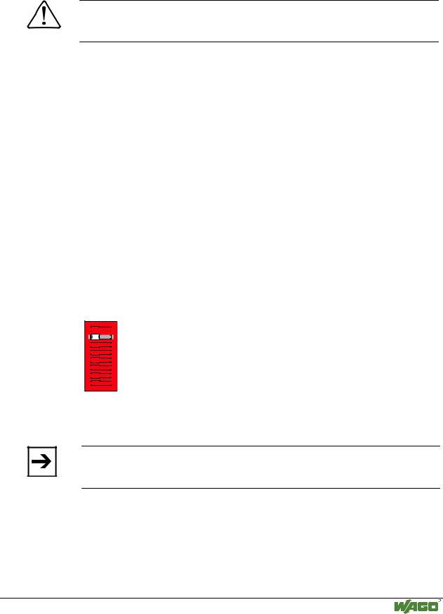
First of all turn all DIP switches to the “OFF” position (module ID = 0), then switch on the voltage supply (DC 24 V power pack) at the fieldbus controller.
1


 ON
ON
2

3


4


5


6


7


8


Fig. 3-14: All DIP switches to “OFF” for checking and setting the Baud rate |
g012442x |
Now the currently set Baud rate is checked and displayed in the top LED group by the blinking of the corresponding LED’s.
Note
If switching on the voltage, when all DIP switches have not been pushed to “OFF”, the existing setting is adopted as the module ID.
Now push the corresponding DIP switches for the desired Baud rate to 'ON', i.e. for the Baud rate 125 kB to DIP switch 3.
WAGO-I/O-SYSTEM 750
CANopen