Материал: m083700e

Внимание! Если размещение файла нарушает Ваши авторские права, то обязательно сообщите нам

CANopen • 121

Network Architecture

If the bus level is in the recessive status, the voltage between CAN_Low and CAN_GND is 2.5 V and also 2.5°V between CAN_High and CAN_GND. This means that the differential voltage is 0 V.

If the bus level is in the dominant status, the voltage between CAN_Low and CAN_GND is 1.5 V and 3.5°V between CAN_High and CAN_GND.

Then differential voltage is approx. 2 V.

Note

When connecting subscribers, ensure that the data lines are not mixed up.

At its conductor ends, the bus cable must always be connected with a matching resistor of 120 Ohm to avoid reflections and, as a result, transmission problems.

This is also required for very short conductor lengths.

750-307

CAN_High


RT


RT


CAN_Low

R = 120 Ohm

T

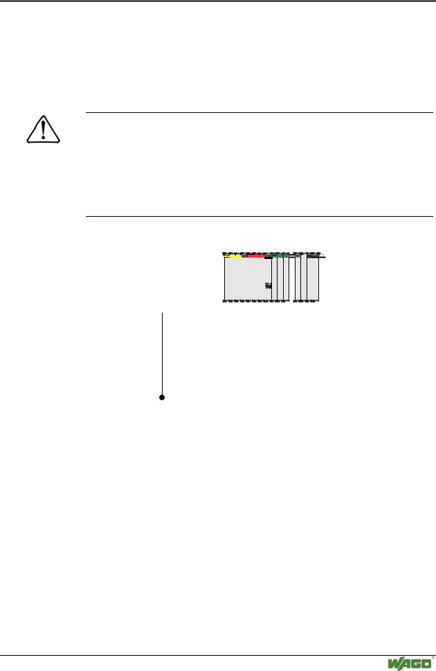
Fig. 5-2: Connection principle of a WAGO fieldbus node to the CAN bus

g012402x

Before starting the buscoupler on the network, the installation should be checked. The physical connection can be checked in the CAN fieldbus with an ohmmeter at any place. You have to remove all connections to other devices except for the terminating resistors.

WAGO-I/O-SYSTEM 750

CANopen
122 • CANopen

Network Architecture

ohmmeter

CAN_High


RT


RT


CAN_Low

GND

R = 120 Ohm

T

Fig. 5-3: Measuring principle to check the CAN bus prior to wiring

g012445e


Measurement


Value


Meaning


GND and CAN_L


infinite


ok.


0


Short-circuit between GND and CAN_L


GND and CAN_H


infinite


o.k.


0


Short-circuit between GND and CAN_H


CAN_L and CAN_H


ca. 60


o.k., 2 terminal resistors in the bus


ca. 120


Only 1 terminal resistor in the bus


< 50


More than 2 terminal resistors in the bus


The CAN bus is 2-wire bus and bus error management can detect a cable break or a short-circuit by the asymmetric operation.

Further information

The CiA provides documents regarding specifications, especially cable specifications in the Internet under:

http://www.can-cia.de

WAGO-I/O-SYSTEM 750

CANopen

CANopen • 123

Network Architecture

5.2.3 Network Topology

To build a simple CANopen network, you need a master (PC with a CANopen fieldbus PCB card), a connection cable and a DC 24 V power pack to ensure the power supply in addition to a CANopen fieldbus node.

The CANopen network is constructed as a line structure with matching resistors (120 Ohm).

In systems having more than two stations, all subscribers are wired in parallel. The maximum length for a conductor branch should not exceed 0.3 m.

Line, Bus


Terminator


Terminator


Network node

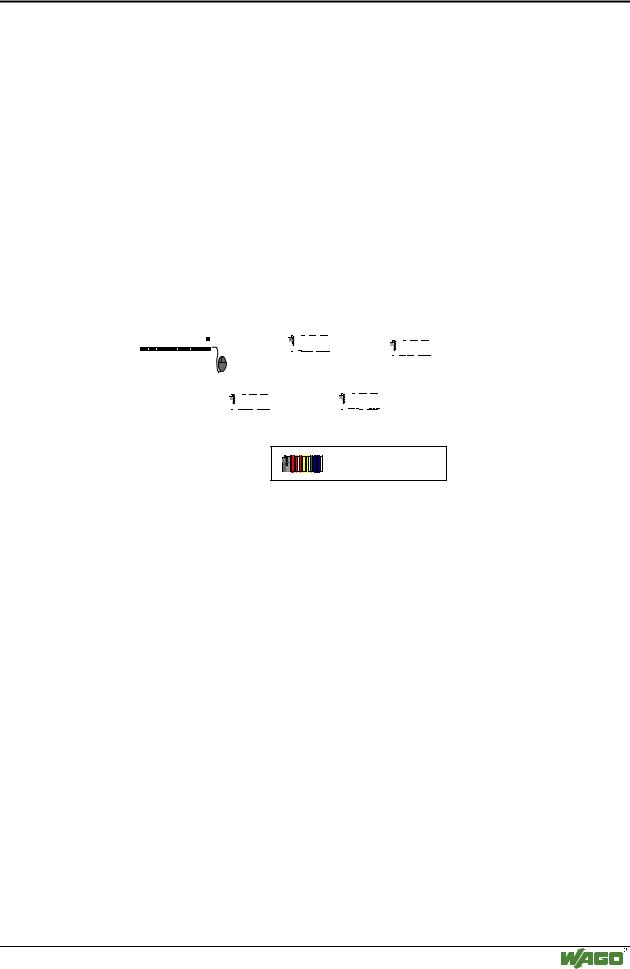
Fig. 5-4: Bus topology of a CANopen network

g012430e

All net subscribers communicate at the same Baud rate. The bus structure permits coupling in and out without side effect of stations, or the step-by- step start-up of the system.

Later extensions have no influence on stations already in operation. The system automatically detects when a subscriber fails or is newly added to the net.

Also branches from the line-shaped bus and as such the establishment of hierarchic net structures are possible via router nodes.

Repeaters can be used to increase the maximum possible number of nodes to 110 and to enlarge the network spatial extension (bus length). Although the network spatial extension depends on the transmission rate, CAN can also be used for spatially extended networks. The data rates achievable are of the same order as with other bus systems. However, the maximum possible cable length is reduced per repeater by 20 - 30 m due to the signal delay.

WAGO-I/O-SYSTEM 750

CANopen

124 • CANopen

Network Architecture

5.2.4 Interface Modules

In a network, all WAGO CANopen fieldbus nodes operate as slaves. The master operation is taken over by a central control system, such as PLC, NC or RC. The connection to fieldbus devices is made via interface modules

Interface modules for programmable logic controls (PLCs) and PC interface PCBs for CANopen are offered by various manufacturers.

5.2.5 Configuration Software

Before a PLC can communicate I/O data with a fieldbus device, the fieldbus controller board has to be configured for each field bus device on the network.

The software for configuring and diagnosing fieldbus networks is delivered with the Interface modules for programmable logic controls (PLCs) or PC interface PCBs for CANopen or it is contained in the used CAN MasterSoftware (e. g. SyCon of the company Firma Hilscher GmbH).

The needed data to the WAGO CANopen couplers and controllers are made available with the merging of the EDS files (Electrical Data Sheet) in the configuration software.

Note

EDS and Symbol files for the configuration of I/O modules are available for free download on the INTERNET Site:

www.wago.com / Service / Downloads / Software / ELECTRONICC / EDS files for CANopen.

WAGO-I/O-SYSTEM 750

CANopen

CANopen • 125

Network Communication

5.3 Network Communication

With CANopen, data transmission, the triggering of events, signalling of error states etc. takes place by means of communication objects. For this purpose, each communication object is assigned a clear COB-ID (Communication Object Identifier) in the network.

The COB ID assignment according to the Device profile DS401 results in accordance with the following table.


10


9


8


7


6


5

4

3


2

1


0


Function


node identifier


code


(0[= all], 1-127)


Communication objects


Function


Object directory


code


index


dec


bin


dec


bin


hex


Broadcast


NMT Command


0


0000


0


messages


Sync message


1


0001


128


80


1005, 1006, 1007


System time


2


0010


256


100


1012, 1013


1


0001


129-255


81-FF


1014, 1015


Peer-to-


Alarm objects


Peer


Tx-PDO1


3


0011


385-511

181-1FF


1800


messages


Rx-PDO1


4


0100


513-639

201-27F


1400


Tx-PDO2


5


0101


641-767

281-2FF


1801


Rx-PDO2


6


0110


769-895

301-37F


1401


Tx-PDO3


7


0111


897-1023

381-3FF


1802


Rx-PDO3


8


1000


1025-1151

401-47F


1402


Tx-PDO4


9


1001


1153-1279

481-4FF


1803


Rx-PDO4


10


1010


1281-1407

501-57F


1403


Tx-SDO


11


1011


1409-1535

581-5FF


1200


Rx-SDO


12


1100


1537-1663

601-67F


1200


node monitoring


14


1110


1793-1919


701-77F


100C, 100D


1016, 1017


The parameters required for the communication objects as well as the parameters and data of the CANopen subscribers are filled in the object directory.

Type and number of objects supported by the node depend on the individual fieldbus coupler.

In addition to several special objects, i.e. for the network management (NMT), for synchronization (SYNC) or for error messages (EMCY), the communication profile contains the two object types PDO and SDO.

The PDOs (process data objects) are used for the transmission of real time data, and the SDOs (service data objects) permit access to the object directory both for reading and writing.

WAGO-I/O-SYSTEM 750

CANopen

Источник: https://studfile.net/preview/16369781/