Материал: SN_Circ243-Rev.2 - Guidelines For The Presentation Of Navigation-Related Symbols Terms And Abbreviations
SN.1/Circ.243/Rev.2
Annex 1, page 4
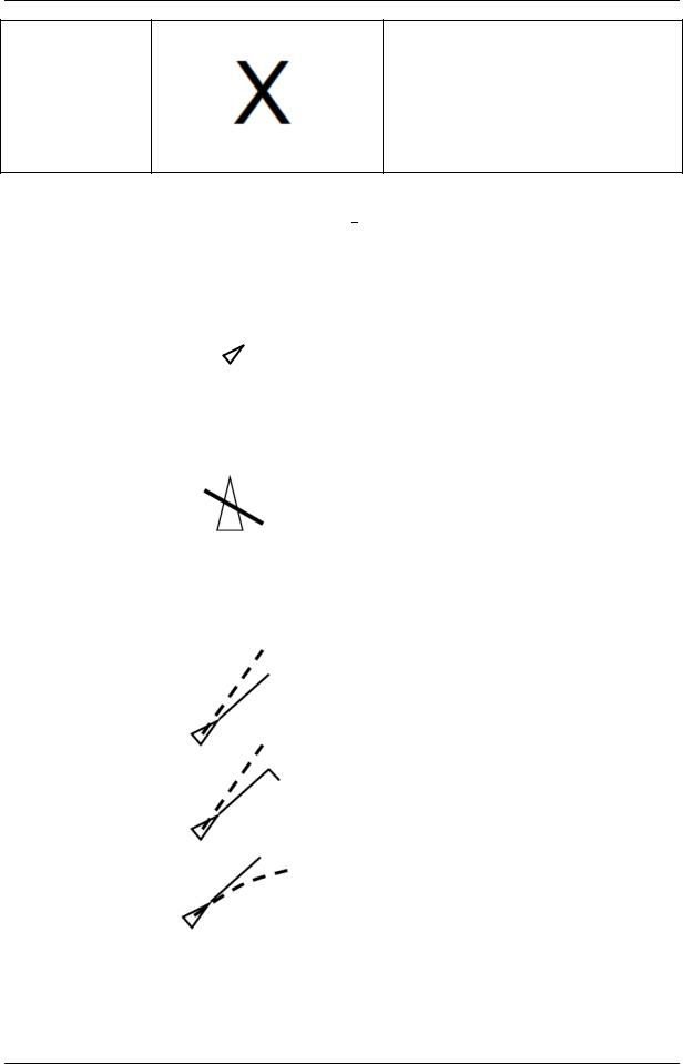
When an internally generated test target is enabled, it should be indicated by the presentation of the large letter "X"
adjacent to the target with the basic Radar test target colour used for the target symbol.
In addition, a bold "X" should be shown in a conspicuous location in the operational display area.
Table 3: AIS Symbols
Topic |
Symbol |
Description |
|
|
|
|
|
An isosceles, acute-angled triangle should be |
|
|
used. The triangle should be oriented by |
AIS target |
|
heading, or COG if heading missing. The |
|
reported position should be located at centre |
|
(sleeping) |
|
|
|
and half the height of the triangle. The symbol |
|
|
|
|
|
|
of the sleeping target should be smaller than |
|
|
that of the activated target. |
|
|
|
Sleeping |
|
Sleeping (activated) AIS target with neither |
|
reported heading nor COG should be |
|
(activated) AIS |
|
|
|
presented as acute isosceles triangle oriented |
|
target with |
|
|
|
toward the top of the operational display area |
|
neither |
|
|
|
with one line crossed through the symbol. |
|
reported |
|
|
|
|
|
heading nor |
|
|
COG |
|
|
|
|
|
|
|
An isosceles, acute-angled triangle should be |
|
|
used. The triangle should be oriented by |
|
|
heading, or COG if heading missing. The |
|
|
reported position should be located at centre |
|
|
and half the height of the triangle. |
|
|
The COG/SOG vector should be displayed as |
|
|
a dashed line with short dashes with spaces |
|
|
approximately twice the line width. Optionally, |
Activated AIS |
|
time increments may be marked along the |
|
vector. |
|
target |
|
|
|
The heading should be displayed as a solid |
|
including |
|
|
|
line thinner than speed vector line style, length |
|
dangerous |
|
|
|
twice of the length of the triangle symbol. |
|
target |
|
|
|
Origin of the heading line is the apex of the |
|
|
|
|
|
|
triangle. |
|
|
The turn should be indicated by a flag of fixed |
|
|
length added to the heading line. |
|
|
A path predictor may be provided as curved |
|
|
vector. For a "Dangerous AIS Target", bold, |
|
|
red (on colour display) solid triangle with |
|
|
course and speed vector, flashing until |
|
|
acknowledged. |
|
|
|
I:\CIRC\SN\01\SN.1-Circ.243-Rev.2.docx
|
|
SN.1/Circ.243/Rev.2 |
|
|
|
Annex 1, page 5 |
|
|
|
|
|
|
|
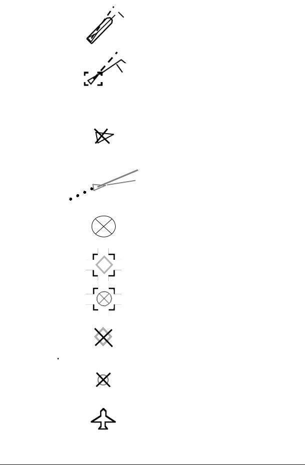
A true scale outline may be added to the |
|
|
|
triangle symbol. It should be: |
|
AIS target – |
|
Located relative to reported position and |
|
true scale |
|
according to reported position offsets, beam |
|
outline |
|
and length. Oriented along target's heading. |
|
|
|
Used on low ranges/large scales. |
|
|
|
|
|
Selected |
|
A square indicated by its corners should be |
|
target |
|
drawn around the activated target symbol. |
|
|
|
|
|
Topic |
Symbol |
Description |
|
|
|
|
|
|
|
Triangle with bold solid cross. The triangle |
|
|
|
should be oriented per last known value. The |
|
|
|
cross should have a fixed orientation. The |
|
Lost target |
|
symbol should flash until acknowledged. |
|
|
|
The target should be displayed without vector, |
|
|
|
heading and rate of turn indication. |
|
|
|
|
|
Target past |
|
Dots, equally spaced by time. |
|
positions |
|
|
|
|
|
|
|
|
|
|
|
AIS Search |
|
|
|
and |
|
A circle containing a cross drawn with solid |
|
Rescue |
|
|
|
|
lines. |
|
|
Transmitter |
|
|
|
|
|
|
|
(AIS-SART) |
|
|
|
Selected AIS |
|
Selected target symbols should be presented |
|
|
as broken squares indicated by their corners, |
|
|
ATON |
|
|
|
|
centred on the selected target symbol. |
|
|
|
|
|
|
|
|
|
|
Selected AIS- |
|
Selected target symbols should be presented |
|
|
as broken squares indicated by their corners, |
|
|
SART |
|
|
|
|
centred on the selected target symbol. |
|
|
|
|
|
|
|
|
|
|
|
|
Lost target symbols should be presented as |
|
Lost AIS |
|
crossed lines centred on the target symbol. |
|
|
The lines should be drawn using a solid line |
|
|
ATON |
|
|
|
|
style and should flash with the required colour |
|
|
|
|
|
|
|
|
red until acknowledged by the user. |
|
|
|
Lost target symbols should be presented as |
|
Lost AIS- |
|
crossed lines centred on the target symbol. |
|
|
The lines should be drawn using a solid line |
|
|
SART |
|
|
|
|
style and should flash with the required colour |
|
|
|
|
|
|
|
|
red until acknowledged by the user. |
|
|
|
An AIS SAR aircraft should be drawn with a |
|
AIS SAR |
|
thin solid outline with the same basic colour as |
|
aircraft |
|
used for target symbols. The symbol should be |
|
|
|
oriented in the direction of the COG. |
|
I:\CIRC\SN\01\SN.1-Circ.243-Rev.2.docx
SN.1/Circ.243/Rev.2
Annex 1, page 6
|
|
|
|
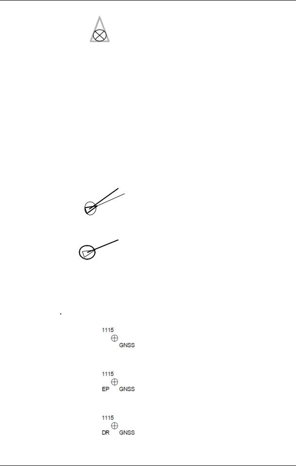
If provided, a search and rescue vessel should |
|
|
|
AIS SAR |
|
|
be presented by having a circle with cross |
|
|
|
vessel |
|
|
drawn with a solid line inside the standard |
|
|
|
|
|
|
activated AIS vessel symbol. |
|
|
|
|
|
|
|
|
|
|
|
|
Table 4: Associated target symbols |
|
||
|
|
|
|
|
|
|
|
Topic |
|
Symbol |
|
Description |
|
|
|
|
|
|
|
|
|
|
|
|
The user may select to present associated |
|
|
|
|
|
|
targets (i.e. activated AIS targets associated |
|
|
|
Associated |
|
|
with tracked radar targets) as either activated |
|
|
|
|
|
AIS target symbols (see symbol: "Activated |
|
||
|
target |
|
|
|
||
|
|
|
AIS Target Including Dangerous Target") or |
|
||
|
|
|
|
|
||
|
|
|
|
tracked radar target symbols (see symbol: |
|
|
|
|
|
|
"Tracked Target including Dangerous Target"). |
|
|
|
|
|
|
|
|
|
|
Associated |
|
|
Alternatively, activated AIS target symbols |
|
|
|
target |
|
|
|
||
|
|
|
representing associated targets may be |
|
||
|
alternative AIS |
|
|
|
||
|
|
|
modified by circumscribing a circle around the |
|
||
|
target |
|
|
|
||
|
|
|
symbols' isosceles triangle. |
|
||
|
symbol |
|
|
|
||
|
|
|
|
|
|
|
|
|
|
|
|
|
|
|
Associated |
|
|
Tracked radar target symbols representing |
|
|
|
target |
|
|
|
||
|
|
|
associated targets may be presented with |
|
||
|
alternative |
|
|
|
||
|
|
|
larger diameter circles modified by inscribing |
|
||
|
radar target |
|
|
|
||
|
|
|
an isosceles triangle inside the symbols' circle. |
|
||
|
symbol |
|
|
|
||
|
|
|
|
|
|
|
|
|
|
Table 5: Other symbols |
|
||
|
|
|
|
|
|
|
|
Topic |
|
Symbol |
|
Description |
|
|
|
|
|
|
|
|
|
|
|
|
|
A plotted position (Fix, EP and DR) |
|
|
|
|
|
|
should be presented as a circle with |
|
|
|
|
|
|
crossed lines centred at the |
|
|
|
|
|
|
position. The length of the crossed |
|
|
|
|
|
|
lines should be the diameter of the |
|
|
|
|
|
|
circle. The circle and crossed lines |
|
|
|
|
|
|
should be drawn using a thin solid |
|
|
|
|
|
|
line style. The position should be |
|
|
Plotted position |
|
|
|
labelled with time and an indication |
|
|
|
|
|
|
of its source for example GNSS, L |
|
|
|
|
|
|
(Loran), R (Radar range), V (Visual |
|
|
|
|
|
|
bearing), VR (Visual bearing and |
|
|
|
|
|
|
Radar range). |
|
|
|
|
|
|
If the position is an estimated |
|
|
|
|
|
|
position, it should also be labelled |
|
|
|
|
|
|
with the letters "EP". |
|
I:\CIRC\SN\01\SN.1-Circ.243-Rev.2.docx
|
|
|
SN.1/Circ.243/Rev.2 |
|
|
|
|
Annex 1, page 7 |
|
|
|
|
|
|
|
Topic |
Symbol |
Description |
|
|
|
|
|
|
|
|
|
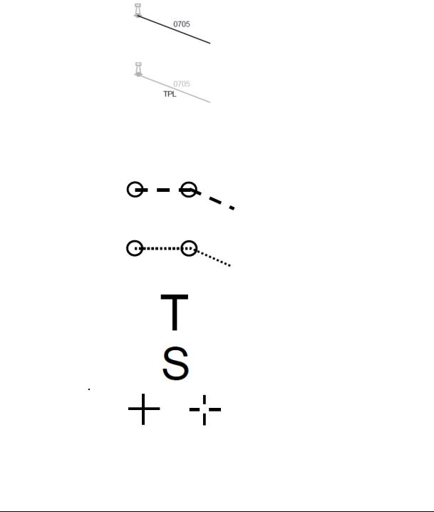
If the position is a dead reckoned |
|
|
|
|
position, it should also be labelled |
|
|
|
|
with the letters "DR". Alphanumeric |
|
|
|
|
text used to label the position |
|
|
|
|
should be the same basic colour as |
|
|
|
|
the symbol. |
|
|
|
|
|
|
|
|
|
A line of position (LOP) should be |
|
|
|
|
presented as a single line |
|
|
|
|
originating from a charted object |
|
|
|
|
and extending towards own ship. |
|
|
|
|
The bearing of the LOP should be |
|
|
|
|
referenced to the CCRP. The LOP |
|
|
|
|
should be drawn using a thin solid |
|
|
|
|
line style. The LOP should be |
|
|
Line of position |
|
labelled with time. If the LOP is |
|
|
|
|
transferred, it may also be labelled |
|
|
|
|
with the letters "TPL" for transferred |
|
|
|
|
position line. Alphanumeric text |
|
|
|
Examples show the default symbol for a |
used to label LOP should be the |
|
|
|
water tower |
same basic colour as the line. A |
|
|
|
|
LOP range observation will be an |
|
|
|
|
arc. |
|
|
|
|
|
|
|
Monitored route |
|
Dashed bold line, waypoints (WPT) |
|
|
|
as circles |
||
|
|
|
||
|
|
|
|
|
|
Planned or |
|
Dotted line, WPT as circles |
|
|
|
|
|
|
|
alternate route |
|
|
|
|
|
|
|
|
|
|
|
Large T on screen |
|
|
Trial manoeuvre |
|
|
|
|
|
|
|
|
|
Simulation |
|
Large S on screen |
|
|
mode |
|
||
|
|
|
|
|
|
|
|
|
|
|
Cursor |
|
Crosshair (two alternatives, one with |
|
|
|
open centred |
||
|
|
|
||
|
|
|
|
|
|
Range rings |
|
Solid circles |
|
|
|
|
|
|
I:\CIRC\SN\01\SN.1-Circ.243-Rev.2.docx
SN.1/Circ.243/Rev.2
Annex 1, page 8
Topic |
Symbol |
Description |
|
|
|
|
|
|
|
Circle. |
|
Variable Range |
|
Additional VRM should be |
|
Markers (VRM) |
|
distinguishable from the primary |
|
|
|
VRM |
|
|
|
|
|
Electronic |
|
Dashed line. |
|
Bearing Lines |
|
Additional EBL should be |
|
(EBL) |
|
distinguishable from primary EBL |
|
|
|
|
|
Acquisition/ |
|
Solid line boundary for an area |
|
Activation area |
|
||
|
|
||
|
|
|
|
|
|
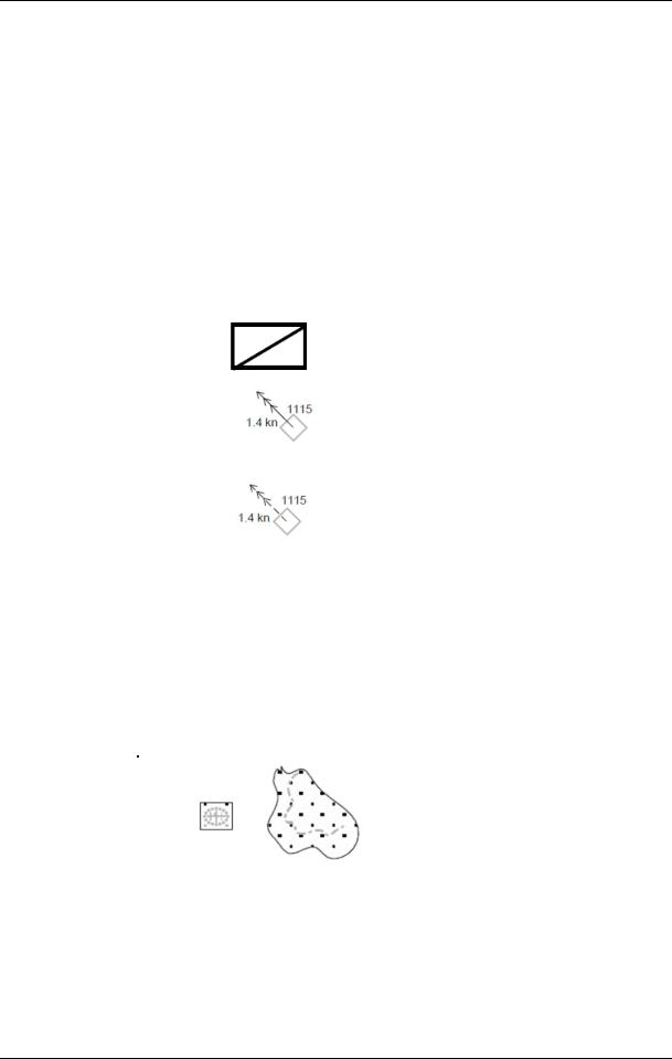
Rectangle with diagonal line, |
|
Event mark |
|
clarified by added text (e.g. "MOB" |
|
|
|
for man overboard cases) |
|
|
|
|
|
|
|
A tidal stream should be presented |
|
|
|
as a single line with three |
|
|
|
arrowheads. The line should |
|
|
|
originate from the charted position |
|
|
|
for which a tidal stream table |
|
|
|
(or tidal stream data) is available. |
|
|
|
The line for an actual tidal stream |
|
|
|
should be drawn using a thin solid |
|
|
Examples show default symbol for a |
line style. The line for a predicted |
|
|
tidal stream should be drawn using |
||
Tidal stream |
point |
||
a thin long dashed line style. The |
|||
|
|
||
|
|
arrowheads for a tidal stream |
|
|
|
should be drawn using a thin solid |
|
|
|
line style. The tidal stream should |
|
|
|
be labelled adjacent to the line with |
|
|
|
the effective strength and time, |
|
|
|
ideally on opposite sides. |
|
|
|
Alphanumeric text used to label the |
|
|
|
tidal stream should be the same |
|
|
|
basic colour as the line. |
|
|
|
A danger highlighted by a mariner |
|
|
|
should be presented as a polygon |
|
|
|
bounding a geographic area |
|
|
|
designated as dangerous to |
|
|
|
navigation, or as a poly-line creating |
|
Mariner entered |
|
a boundary around such an area. |
|
Examples show the default symbol for a |
The boundary of the polygon, or |
||
danger |
|||
mariner entered danger highlighting a |
poly-line, should be drawn using a |
||
|
|||
|
dangerous wreck at an unknown depth |
thick solid line style. Recommended |
|
|
bounded by a rectangular danger |
colour: red. The polygon, or |
|
|
highlight and an outcropping of land |
bounded area, should be filled with |
|
|
bounded by a user-entered danger |
a transparent fill using the same |
|
|
highlight |
colour as the polygon or poly-line. |
|
|
|
I:\CIRC\SN\01\SN.1-Circ.243-Rev.2.docx