Материал: SN_Circ243-Rev.2 - Guidelines For The Presentation Of Navigation-Related Symbols Terms And Abbreviations

E
4 ALBERT EMBANKMENT
LONDON SE1 7SR
Telephone: +44 (0)20 7735 7611 Fax: +44 (0)20 7587 3210
SN.1/Circ.243/Rev.2
14 June 2019
GUIDELINES FOR THE PRESENTATION OF
NAVIGATION-RELATED SYMBOLS, TERMS AND ABBREVIATIONS
1The Maritime Safety Committee, at its ninety-third session (14 to 23 May 2014), approved the Amended Guidelines for the presentation of navigational-related symbols, terms and abbreviations (SN/Circ.243/Rev.1) prepared by the Sub-Committee on Safety of Navigation (NAV) at its fifty-ninth session (2 to 6 September 2013) and encouraged their use for all shipborne navigational systems and equipment.
2The Sub-Committee on Navigation, Communications and Search and Rescue (NCSR), at its sixth session (16 to 25 January 2019), with a view to harmonizing the requirements for the presentation of navigation-related information on the bridge which would ensure that all navigational displays adopt a consistent human-machine interface philosophy and implementation, agreed to revised Guidelines for the presentation of navigation-related symbols, terms and abbreviations.
3The Maritime Safety Committee, at its 101st session (5 to 14 June 2019), concurred with the Sub-Committee's views, and approved the revised Guidelines for the presentation of navigation-related symbols and the revised Guidelines for the presentation of navigation-related terms and abbreviations, as set out in annexes 1 and 2, respectively.
4This circular does not revoke SN.1/Circ.243/Rev.1, however, for the purpose of applying resolutions:
.1 MSC.191(79), the Guidelines in SN.1/Circ.243/Rev.1 are to be applied to:
.1 |
radar equipment, electronic chart display and information systems |
|
|
(ECDIS) and integrated navigation systems (INS) installed before |
|
|
1 |
January 2024; and |
.2 |
all other navigational displays on the bridge of a ship installed before |
|
|
1 |
July 2025; and |
.2 MSC.191(79), as amended by resolution MSC.466(101), the Guidelines in SN.1/Circ.243/Rev.2 are to be applied to equipment installed on or after the dates specified in paragraph 4.1 above.
5 Member States are invited to bring the revised Guidelines to the attention of all parties concerned.
***
I:\CIRC\SN\01\SN.1-Circ.243-Rev.2.docx

SN.1/Circ.243/Rev.2
Annex 1, page 1
ANNEX 1
GUIDELINES FOR THE PRESENTATION OF NAVIGATION-RELATED SYMBOLS
1 Purpose
The purpose of these Guidelines is to provide guidance on the appropriate use of navigation-related symbols to achieve a harmonized and consistent presentation.
2 Scope
The use of these Guidelines will ensure that the symbols used for the display of navigation-related information on all shipborne navigational systems and equipment are presented in a consistent and uniform manner.
3 Application
These Guidelines apply to all shipborne navigational systems and equipment. The symbols listed in the appendix should be used for the display of navigation-related information to promote consistency in the symbol presentation on navigational equipment. The symbols listed in the appendix should replace symbols which are currently contained in existing performance standards. Where a standard symbol is not available, another symbol may be used, but this symbol should not conflict with the symbols listed in the appendix.
I:\CIRC\SN\01\SN.1-Circ.243-Rev.2.docx
SN.1/Circ.243/Rev.2
Annex 1, page 2
APPENDIX
NAVIGATION-RELATED SYMBOLS
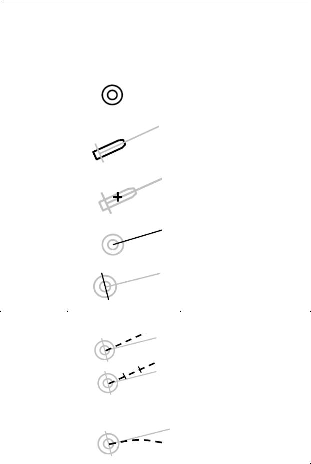
Table 1: Own ship symbols
|
Topic |
Symbol |
Description |
|
|
|
|
|
|
|
|
|
Double circle, located at own ship's |
|
|
|
|
reference position. |
|
|
Own ship |
|
Use of this symbol is optional, if own |
|
|
|
ship position is shown by the |
||
|
|
|
||
|
|
|
combination of Heading Line and |
|
|
|
|
Beam Line. |
|
|
|
|
True scale outline located relative to |
|
|
|
|
own ship's reference position, oriented |
|
|
Own ship true |
|
along own ship's heading. |
|
|
scale outline |
|
Used on small ranges/large scales. |
|
|
|
|
||
|
|
|
|
|
|
|
|
Cross, located on a true scale outline |
|
|
Own ship radar |
|
of the ship at the Physical location of |
|
|
|
the radar antenna that is the current |
||
|
antenna position |
|
||
|
|
source of displayed radar video. |
||
|
|
|
||
|
|
|
|
|
|
|
|
Solid line thinner than the speed |
|
|
Own ship |
|
vector line style, draw to the bearing |
|
|
|
ring of fixed length, if the bearing ring |
||
|
heading line |
|
||
|
|
is not displayed. Origin is at own |
||
|
|
|
||
|
|
|
ship's reference point. |
|
|
|
|
Solid line of fixed length; optionally |
|
|
Own ship beam |
|
length variable by operator. Midpoint |
|
|
|
at own ship's reference point. |
||
|
line |
|
||
|
|
|
|
|
|
|
|
|
|
|
|
|
Dashed line – short dashes with |
|
|
|
|
spaces approximately twice the line |
|
|
|
|
width of heading line. |
|
|
|
|
Time increments between the origin |
|
|
Own ship speed |
|
and endpoint may optionally be |
|
|
|
marked along the vector using short |
||
|
vector |
|
||
|
|
intersecting lines. |
||
|
|
|
||
|
|
|
To indicate Water/Ground stabilization |
|
|
|
|
optionally one arrowhead for water |
|
|
|
|
stabilization and two arrowheads for |
|
|
|
|
ground stabilization may be added. |
|
|
Own ship path |
|
A curved vector may be provided as a |
|
|
|
path predictor. |
||
|
prediction |
|
||
|
|
|
|
|
|
|
|
|
|
|
|
|
|
|
I:\CIRC\SN\01\SN.1-Circ.243-Rev.2.docx
|
|
|
|
|
|
|
|
SN.1/Circ.243/Rev.2 |
||
|
|
|
|
|
|
|
|
Annex 1, page 3 |
|
|
|
|
|
|
|
|
|
|
|
|
|
|
|
Topic |
|
|
Symbol |
|
Description |
|||
|
|
|
|
|
|
|
|
|
|
|
|
|
|
|
|
|
|
|
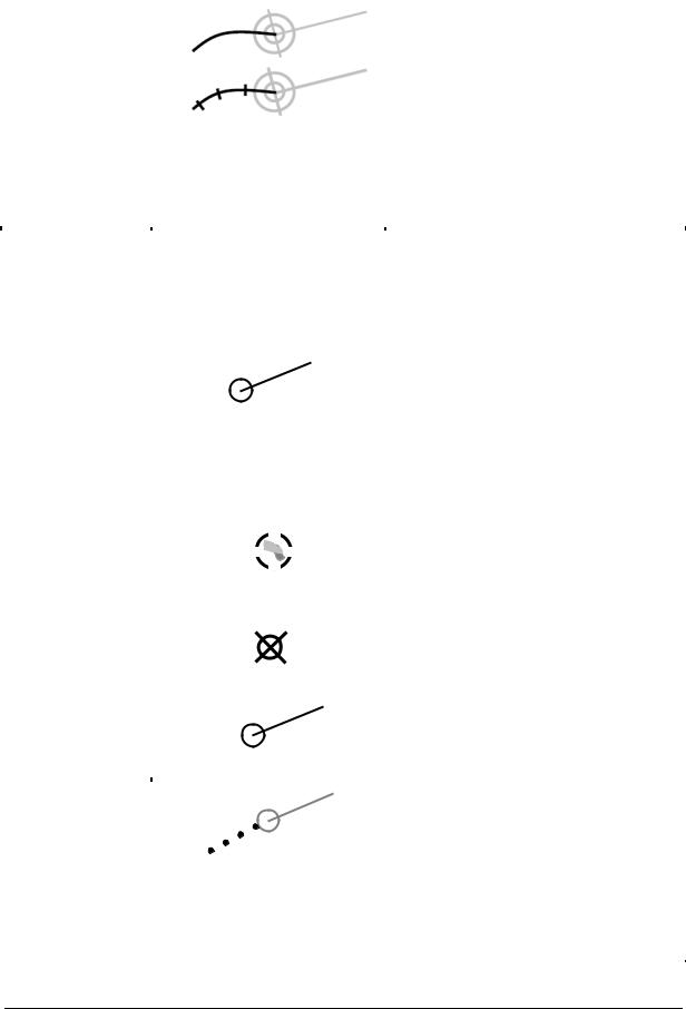
Thick line for primary source. Thin line |
||
|
|
|
|
|
|
|
|
for secondary source. |
||
|
|
Own ship |
|
|
|
|
|
Optional time marks are allowed. |
||
|
|
|
|
|
|
|
|
|
|
|
|
|
past track |
|
|
|
|
|
|
|
|
|
|
|
|
|
|
|
|
|
|
|
|
|
|
|
Table 2: Tracked Radar Target Symbols |
||||||
|
|
|
|
|
|
|
|
|
||
|
|
Topic |
|
Symbol |
|
Description |
|
|||
|
|
|
|
|
|
|
|
|
||
|
|
|
|
|
|
|
Solid filled or unfilled circle located at |
|
||
|
|
|
|
|
|
|
target position. |
|
||
|
|
|
|
|
|
|
The course and speed vector should be |
|
||
|
|
|
|
|
|
|
displayed as dashed line, with short |
|
||
|
|
Tracked target |
|
|
|
dashes with spaces approximately twice |
|
|||
|
|
|
|
|
the line width. |
|
||||
|
|
including |
|
|
|
|
||||
|
|
|
|
|
Optionally, time increments may be |
|
||||
|
|
dangerous target |
|
|
|
|
||||
|
|
|
|
|
marked along the vector. |
|
||||
|
|
|
|
|
|
|
|
|||
|
|
|
|
|
|
|
For a "Dangerous Target", bold, red |
|
||
|
|
|
|
|
|
|
(on colour display) solid circle with |
|
||
|
|
|
|
|
|
|
course and speed vector, flashing until |
|
||
|
|
|
|
|
|
|
acknowledged. |
|
||
|
|
|
|
|
|
|
|
|
||
|
|
|
|
|
|
|
Circle segments in the acquired target |
|
||
|
|
Target in |
|
|
|
state. |
|
|||
|
|
|
|
|
For automatic acquisition, bold circle |
|
||||
|
|
acquisition state |
|
|
|
|
||||
|
|
|
|
|
segments, flashing and red (on colour |
|
||||
|
|
|
|
|
|
|
|
|||
|
|
|
|
|
|
|
display) until acknowledged. |
|
||
|
|
|
|
|
|
|
|
|
||
|
|
Lost target |
|
|
|
Bold lines across the circle, flashing until |
|
|||
|
|
|
|
|
acknowledged. |
|
||||
|
|
|
|
|
|
|
|
|||
|
|
|
|
|
|
|
|
|
||
|
|
Selected target |
|
|
|
A square indicated by its corners |
|
|||
|
|
|
|
|
|
|||||
|
|
|
|
|
centred around the target symbol. |
|
||||
|
|
|
|
|
|
|
|
|||
|
|
|
|
|
|
|
|
|
|
|
|
|
Target past |
|
|
|
Dots, equally spaced by time. |
|
|||
|
|
positions |
|
|
|
|
||||
|
|
|
|
|
|
|
|
|
||
|
|
|
|
|
|
|
|
|
||
|
|
|
|
|
R |
Large R adjacent to designated tracked |
|
|||
|
|
Tracked reference |
|
target. |
|
|||||
|
|
|
|
|
|
|||||
|
|
target |
|
|
|
Multiple reference targets should be |
|
|||
|
|
|
|
|
|
|
marked as R1, R2, R3, etc. |
|
||
|
|
|
|
|
|
|
|
|
|
|
I:\CIRC\SN\01\SN.1-Circ.243-Rev.2.docx