Материал: m083700e

Fieldbus Controller 750-837, /02x-000, 750-838, /02x-000 |
• 41 |
Description |
|
|
|
According to the IEC 61131-3 programming, data processing occurs locally in the PFC. The link results created in this manner can be put out directly to the actuators or transmitted to the higher ranking control system via the bus.
The process data exchange is made via PDOs and SDOs. The controller supports 32 Tx and 32 Rx PDOs, as well as 2 server and 16 client SDOs for sending process data via the CANopen fieldbus.
The programmer has access to all fieldbus and I/O data.
In the initialization phase the fieldbus controller determines the physical structure of the node and creates a process image from this with all inputs and outputs. This could involve a mixed arrangement of analog (word by word data exchange) and digital (byte by byte data exchange) modules.
The local process image is subdivided into an input and output data area.
The data of the analog modules are mapped into the PDOs according to the order of their position downstream of the bus coupler. The bits of the digital modules are compiled to form bytes and also mapped into PDOs. Should the number of digital I/Os exceed 8 bits, the coupler automatically starts another byte.
The entries in the object directory can be mapped to the 32 RxPDOs and 32 TxPDOs as required. The entire input and output data area can be transmitted with the SDOs.
“Spacer modules” can be set using the software.
WAGO-I/O-SYSTEM 750
CANopen
42• Fieldbus Controller 750-837, /02x-000, 750-838, /02x-000 Hardware
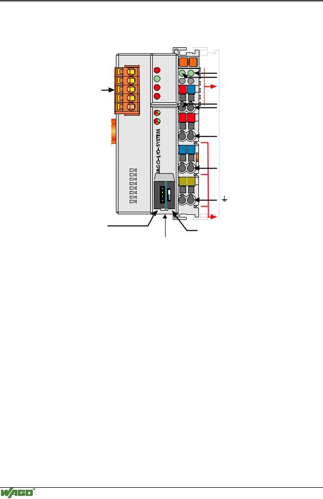
3.1.2 Hardware
3.1.2.1 View
Fieldbus connection Series 231 (MCS)
DIP switch for Node ID  and baud rate
Configuration and programming interface
|
|
|
|
|
|
1 |
|
ON |
2 |
|
|
|
|
|
3 |
|
|
|
|
|
4 |
|
|
|
|
|
5 |
|
|
|
|
|
6 |
|
|
|
|
|
7 |
|
|
|
|
|
8 |
|
|
|
|
|
|
|
|
|
|
|
Status |
|
|
|
|
voltage supply |
|
CANopen |
01 |
02 |
-Power jumper |
|
|
||||
STOP |
A |
|
contacts |
|
|
C |
|||
|
|
-System |
||
RUN |
B |
|
||
|
D |
|||
|
|
|||
|
|
|
||
TX |
24V |
0V |
Data contacts |
|
OVERFLOW |
Supply |
|||
RX |
|
|
||
|
|
|
24V |
|
I/O |
|
|
0V |
|
+ |
+ |
Supply via |
||
USR |
||||
|
|
power jumper |
||
|
|
|
contacts |
|
|
|
|
24V |
|
|
- |
- |
|
|
-837 |
|
|
0V |
|
750 |
|
|
||
|
|
|
PE 
 PE
PE
Power jumper contacts
operating
mode switch
flap opened
Fig. 3-1: Fieldbus controller 750-837 CANopen |
g083700e |
The fieldbus controller is comprised of:
•Device supply with an internal system supply module as well as power jumper contacts for the field supply via assembled I/O modules
•Fieldbus interface with the bus connection
•DIP switch for baud rate and node ID
•Display elements (LEDs) for status display of the operation, the bus communication, the operating voltages as well as for fault messages and diagnosis
•Configuration and programming interface and operating mode switch
•Electronics for communication with the I/O modules (internal bus) and the fieldbus interface
WAGO-I/O-SYSTEM 750
CANopen
|
|
Fieldbus Controller 750-837, /02x-000, 750-838, /02x-000 • 43 |
|
|
|
Hardware |
|
|
|
|
|
3.1.2.2 Variants |
|
|
|
|
|
|
|
|
Item No. |
Description |
|
|
750-837 |
CANopen Controller with MCS Fieldbus connection, |
|
|
|
PFC Memory: RAM 64 kB, FLASH: 64/128 kB with/without Online change |
|
|
|
|
|
|
750-837/020-000 |
CANopen Controller with MCS Fieldbus connection, |
|
|
|
PFC Memory: RAM 192 kB, FLASH: 128/256 kB with/without Online change |
|
|
|
|
|
|
750-837/021-000 |
CANopen Controller with MCS Fieldbus connection, |
|
|
|
PFC Memory: RAM 832 kB, FLASH: 320/640 kB with/without Online change |
|
|
|
|
|
|
750-838 |
CANopen Controller with D-SUB Fieldbus connection, |
|
|
|
PFC Memory: RAM 64 kB, FLASH: 64/128 kB with/without Online change |
|
|
|
|
|
|
750-838/020-000 |
CANopen Controller with D-SUB Fieldbus connection, |
|
|
|
PFC Memory: RAM 192 kB, FLASH: 128/256 kB with/without Online change |
|
|
|
|
|
|
750-838/021-000 |
CANopen Controller with D-SUB Fieldbus connection, |
|
|
|
PFC Memory: RAM 832 kB, FLASH: 320/640 kB with/without Online change |
|
|
|
|
|
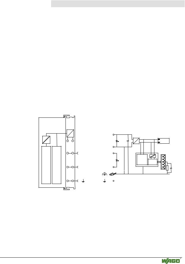
3.1.2.3 Device supply
The supply is via fed in terminal blocks with CAGE CLAMP® connection.
Device supply is intended for system supply and field side supply.
|
|
1 |
5 |
FIELDBUSINTERFACE |
ELECTRONICS |
2 |
6 |
4 |
8 |
||
|
|
3 |
7 |
|
|
|
750-837 |
Fig. 3-2: Device supply
|
24V |
|
|
24V/0V |
10nF |
DC |
Bus |
|
|||
DC |
modules |
||
|
|
|
0V
24V 24V
ELECTRONICS FIELDBUS
INTERFACE
1) 2)
0V |
0V |
10nF
1) 1MΩ
2) 10nF/500V
g083701e
The integrated internal system supply module generates the necessary voltage to supply the electronics and the connected I/O modules.
The fieldbus interface is supplied with electrically isolated voltage from the internal system supply module.
WAGO-I/O-SYSTEM 750
CANopen
44• Fieldbus Controller 750-837, /02x-000, 750-838, /02x-000 Hardware
3.1.2.4 Fieldbus connection
750-837, |
The CAN interface of the Fieldbus controllers 750-837, /020- |
|
000, /021-000 are designed as an Open Style connection, |
||
/020-000, |
||
MCS (Multi Connection System; Series 231) |
||
/021-000 |
||
(included in delivery). |
||
|
||
750-838, |
The Fieldbus controllers 750-838, /020-000, /021-000 posses a |
|
/020-000, |
9-pole D-SUB-plug connector for the field bus connection |
|
/021-000 |
(Item No.: 750-963 not included in delivery). |
The connection point is lowered in such a way that after a connector is inserted, installation in an 80 mm high switchbox is possible.
The electrical isolation between the fieldbus system and the electronics is made via the DC/DC converter and the optocoupler in the fieldbus.
For both fieldbus controller the shield on the CANopen communication cable must be connected to drain. The shield is connected via a 1 MΩ resistor to ground (earth) (rail carrier contact). A connection of low impedance between shield and ground (earth) can only be made externally (for example by a supply terminal block). It is recommended to have a central ground (earth) contact for the whole CANbus shield.
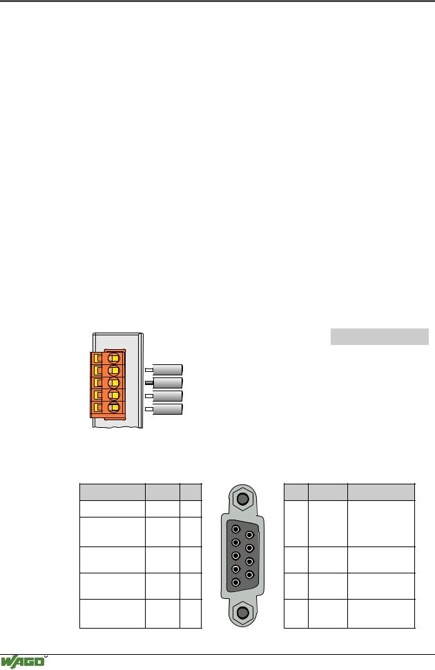
3.1.2.4.1 MCS (750-837, /020-000, /021-000)

 CAN_High
drain

 CAN_Low

 CAN_GND
Pin |
Signal |
Description |
1 |
CAN_V+ |
Not used |
|
|
|
2 |
CAN_H |
CAN Signal High |
3 |
Drain Shield |
Shield connection |
|
|
|
4 |
CAN_L |
CAN Signal Low |
5 |
GND |
Ground |
|
|
|
Fig. 3-3: Pin assignment for fieldbus connection Series 231 (MCS) |
g012400x |
3.1.2.4.2 D-SUB (750-838, /020-000, /021-000)
Description |
Signal |
Pin |
Pin Signal |
Description |
Not used |
- |
1 |
|
|
CAN Signal Low CAN_L |
2 |
1 |
6 |
6 |
- |
Not used |
||
2 |
||||||||
|
|
|
7 |
|
|
|
||
|
|
|
3 |
|
|
|
||
Ground |
GND |
3 |
8 |
7 |
CAN_H |
CAN Signal High |
||
4 |
||||||||
|
|
|
9 |
|
|
|
||
Not used |
- |
4 |
5 |
8 |
- |
|
||
|
Not used |
|||||||
Shield |
Drain |
5 |
|
|
9 |
CAN_V+ Not used |
||
connection |
Shield |
|
|
|
|
|
|
|
Fig. 3-4: |
Pin assignment for fieldbus connection D-SUB |
g012231d |
||||||
WAGO-I/O-SYSTEM 750
CANopen
Fieldbus Controller 750-837, /02x-000, 750-838, /02x-000 |
• 45 |
Hardware |
|
|
|
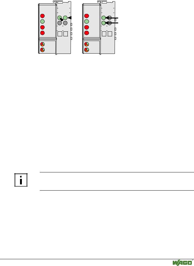
3.1.2.5 Display elements
The operating condition of the fieldbus controller or node is displayed via light diodes (LED).
|
CANopen |
|
|
01 |
|
02 |
|
|
|
|
CANopen |
|
01 |
|
02 |
|
|
|
|
|
||
|
|
|
|
|
|
|
|
|
|
|
|
|
|
|
||||||||
|
|
|
|
|
|
|
|
|
|
|
|
|
|
|
|
|
|
|
|
|
|
|
|
STOP |
|
A |
|
C |
|
STOP |
A |
|
|
A |
|
||||||||||
|
|
|
|
|
|
|
C |
|
|
|
|
|
|
C |
|
|
||||||
|
|
|
|
|
|
|
|
|
|
|
|
|
|
|
||||||||
|
RUN |
|
B |
|
|
A |
|
RUN |
B |
|
B |
|
||||||||||
|
|
|
|
|
|
D |
|
|
|
|
|
D |
|
|
|
|||||||
|
|
|
|
|
|
|
|
|
|
|
|
|||||||||||
|
TX |
|
|
24V |
0V |
|
|
|
|
TX |
|
24V |
|
0V |
|
|
|
|
|
|||
|
|
|
|
|
|
|
|
|
|
|
|
|||||||||||
|
OVERFLOW |
|
|
|
|
|
|
OVERFLOW |
|
|
|
|
|
|
|
|||||||
|
RX |
|
|
|
|
|
|
|
|
|
|
RX |
|
|
|
|
|
|
|
|
|
|
|
|
|
|
|
|
|
|
|
|
|
|
|
|
|
|
|
|
|
|
|
||
|
I/O |
|
|
|
|
|
|
|
|
|
|
I/O |
|
|
|
|
|
|
|
|
|
|
|
|
|
|
|
|
|
|
|
|
|
|
|
|
|
|
|
|
|
|
|
||
|
|
|
|
|
|
|
|
|
|
|
|
|
|
|
|
|
|
|
|
|
||
|
|
|
|
|
|
|
|
|
|
|
|
|
|
|
|
|
|
|
|
|
||
|
USR |
|
|
|
|
|
|
|
|
|
|
USR |
|
|
|
|
|
|
|
|
|
|
Fig. 3-5: |
Display elements |
|
|
|
|
|
|
|
|
g083702x |
|
|||||||||||
|
|
|
|
|
|
|
|
|
|
|
|
|
|
|
|
|
|
|||||
|
LED |
|
|
Color |
|
|
Meaning |
|
|
|
|
|
|
|
|
|
|
|||||
|
STOP |
|
|
red |
|
|
Fieldbus controller / node is in the state STOP |
|
||||||||||||||
|
|
|
|
|
|
|
|
|||||||||||||||
|
RUN |
|
|
green |
|
Fieldbus controller / node is in the state OPERATIONAL |
|
|||||||||||||||
|
|
|
|
|
|
|
|
|||||||||||||||
|
Tx- |
|
|
red |
|
CAN transmitter buffer is full. |
|
|||||||||||||||
|
Overflow |
|
|
|
|
|
|
|
|
|
|
|
|
|
|
|
|
|
|
|
|
|
|
|
|
|
|
|
|
|
|||||||||||||||
|
Rx- |
|
|
red |
|
CAN receiver buffer is full. |
|
|||||||||||||||
|
Overflow |
|
|
|
|
|
|
|
|
|
|
|
|
|
|
|
|
|
|
|
|
|
|
|
|
|
|
|
|
|
|||||||||||||||
|
IO |
|
|
red/green |
|
The 'I/O'-LED indicates the operation of the node and signals faults |
|
|||||||||||||||
|
|
|
|
/orange |
|
|
encountered. |
|
|
|||||||||||||
|
|
|
|
|
|
|
|
|||||||||||||||
|
USR |
|
|
red/green |
|
The 'USR' LED can be selected by a user program in a programma- |
|
|||||||||||||||
|
|
|
|
/orange |
|
|
ble fieldbus controller |
|
|
|||||||||||||
|
|
|
|
|
|
|
|
|||||||||||||||
|
A |
|
|
green |
|
Status of the operating voltage system |
|
|||||||||||||||
|
|
|
|
|
|
|
|
|||||||||||||||
|
B or C |
|
|
green |
|
Status of the operating voltage – power jumper contacts |
|
|||||||||||||||
|
|
|
|
|
|
|
|
|
|
|
|
(LED position is manufacturing dependent) |
|
|||||||||
|
|
|
|
|
|
|
|
|
|
|
|
|
|
|
|
|
|
|
|
|
|
|
More Information
The evaluation of the displayed LED signals is described in Chapter 3.1.8 "LED Display"
WAGO-I/O-SYSTEM 750
CANopen