Материал: m083700e
The WAGO-I/O-SYSTEM 750 • 31
Power Supply
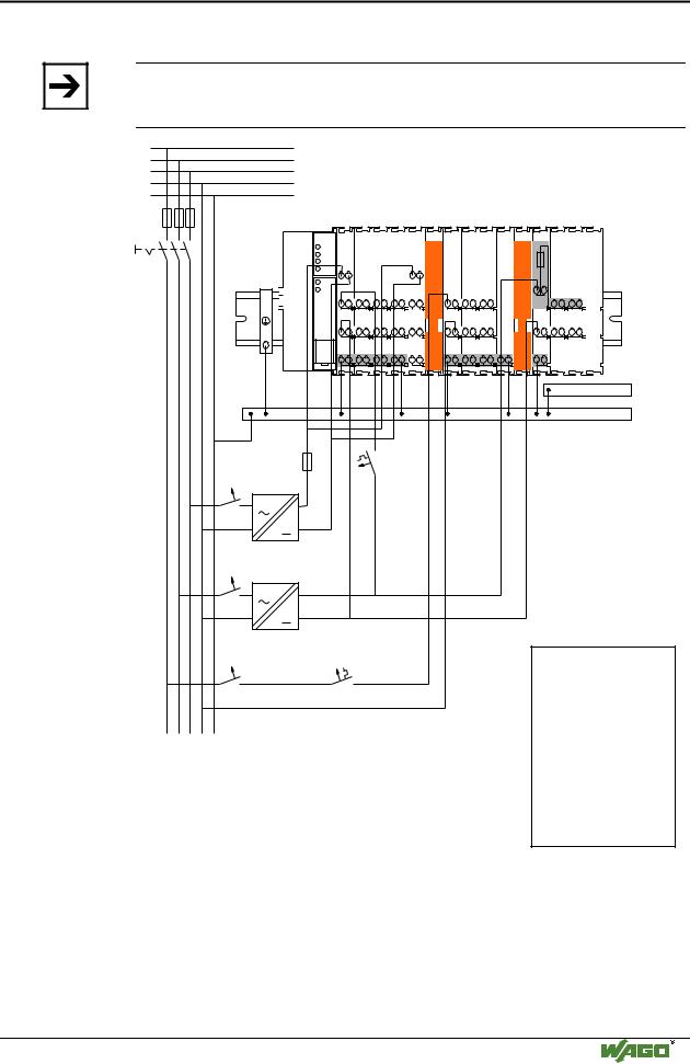
2.7.5 Supply example
Note
The system supply and the field supply should be separated in order to ensure bus operation in the event of a short-circuit on the actuator side.
L1
L2
L3
N
PE
|
|
|
|
|
|
|
|
a) |
|
b) 1) c) |
1) d) |
|||
|
|
|
|
|
|
|
|
|
|
|
|
|
|
|
|
|
|
|
|
|
|
|
|
|
|
|
|
|
|
|
|
|
|
|
|
|
|
|
|
|
|
|
|
|
|
|
|
|
|
|
|
|
|
|
|
|
|
|
|
|
|
|
|
|
|
|
|
|
|
|
|
|
|
|
|
|
|
|
|
|
|
|
|
|
|
|
|
|
|
|
|
|
|
|
|
|
|
|
|
|
|
|
|
|
|
|
|
|
|
|
|
|
|
|
|
|
|
|
|
|
|
|
|
|
|
|
|
|
|
|
|
|
|
|
|
|
|
|
|
|
|
|
|
|
|
|
|
|
|
|
|
|
|
|
|
|
|
|
|
|
|
|
|
|
|
|
|
|
|
|
|
|
|
|
|
|
|
|
|
|
|
|
|
|
|
|
|
|
|
|
|
|
|
|
|
|
|
|
|
|
|
|
|
|
|
|
|
|
|
|
|
|
|
|
|
|
|
|
|
|
|
|
|
|
750-400 |
750-410 |
750-401 |
750-613 |
750-616 |
750-612 |
750-512 |
750-512 |
750-513 |
750-616 |
750-610 |
750-552 |
750-630 |
750-600 |
2) |
2) |
Shield (screen) bus
Main ground bus
System
Supply
230V
24V
Field
Supply
10 A
230V
24V
Field |
1) |
Separation module |
|
Supply |
|||
|
recommended |
||
|
|
||
|
2) |
Ring-feeding |
|
10 A |
|
recommended |
a) Power Supply
on coupler / controller via external Supply Module
b) Internal System Supply Module c) Supply Module
passive
d) Supply Module with fuse carrier/ diagnostics
Fig. 2-22: Supply example |
g0xxx04e |
WAGO-I/O-SYSTEM 750
CANopen
32 • The WAGO-I/O-SYSTEM 750
Power Supply
2.7.6 Power Supply Unit
The WAGO-I/O-SYSTEM 750 requires a 24 V direct current system supply with a maximum deviation of -15% or +20 %.
Recommendation
A stable network supply cannot be taken for granted always and everywhere. Therefore, regulated power supply units should be used in order to guarantee the quality of the supply voltage.
A buffer (200 µF per 1 A current load) should be provided for brief voltage dips. The I/O system buffers for approx 1 ms.
The electrical requirement for the field supply is to be determined individually for each power supply point. Thereby all loads through the field devices and bus modules should be considered. The field supply as well influences the bus modules, as the inputs and outputs of some bus modules require the voltage of the field supply.
Note
The system supply and the field supply should be isolated from the power supplies in order to ensure bus operation in the event of short circuits on the actuator side.
WAGO products |
Description |
Article No. |
|
787-903 |
Primary switched - mode, DC 24 V, 5 A |
|
wide input voltage range AC 85-264 V |
|
PFC (Power Factor Correction) |
|
|
787-904 |
Primary switched - mode, DC 24 V, 10 A |
|
wide input voltage range AC 85-264 V |
|
PFC (Power Factor Correction) |
|
|
787-912 |
Primary switched - mode, DC 24 V, 2 A |
|
wide input voltage range AC 85-264 V |
|
PFC (Power Factor Correction) |
|
|
|
Rail-mounted modules with universal mounting carrier |
288-809 |
AC 115 V / DC 24 V; 0,5 A |
288-810 |
AC 230 V / DC 24 V; 0,5 A |
288-812 |
AC 230 V / DC 24 V; 2 A |
288-813 |
AC 115 V / DC 24 V; 2 A |
|
|
WAGO-I/O-SYSTEM 750
CANopen
The WAGO-I/O-SYSTEM 750 • 33
Grounding
2.8 Grounding
2.8.1 Grounding the DIN Rail
2.8.1.1 Framework Assembly
When setting up the framework, the carrier rail must be screwed together with the electrically conducting cabinet or housing frame. The framework or the housing must be grounded. The electronic connection is established via the screw. Thus, the carrier rail is grounded.
Attention
Care must be taken to ensure the flawless electrical connection between the carrier rail and the frame or housing in order to guarantee sufficient grounding.
2.8.1.2 Insulated Assembly
Insulated assembly has been achieved when there is constructively no direct conduction connection between the cabinet frame or machine parts and the carrier rail. Here the earth must be set up via an electrical conductor.
The connected grounding conductor should have a cross section of at least 4 mm2.
Recommendation
The optimal insulated setup is a metallic assembly plate with grounding connection with an electrical conductive link with the carrier rail.
The separate grounding of the carrier rail can be easily set up with the aid of the WAGO ground wire terminals.
Article No. |
Description |
283-609 |
Single-conductor ground (earth) terminal block make an automatic |
|
contact to the carrier rail; conductor cross section: 0.2 -16 mm2 |
|
Note: Also order the end and intermediate plate (283-320) |
|
|
WAGO-I/O-SYSTEM 750
CANopen
34 • The WAGO-I/O-SYSTEM 750
Grounding
2.8.2 Grounding Function
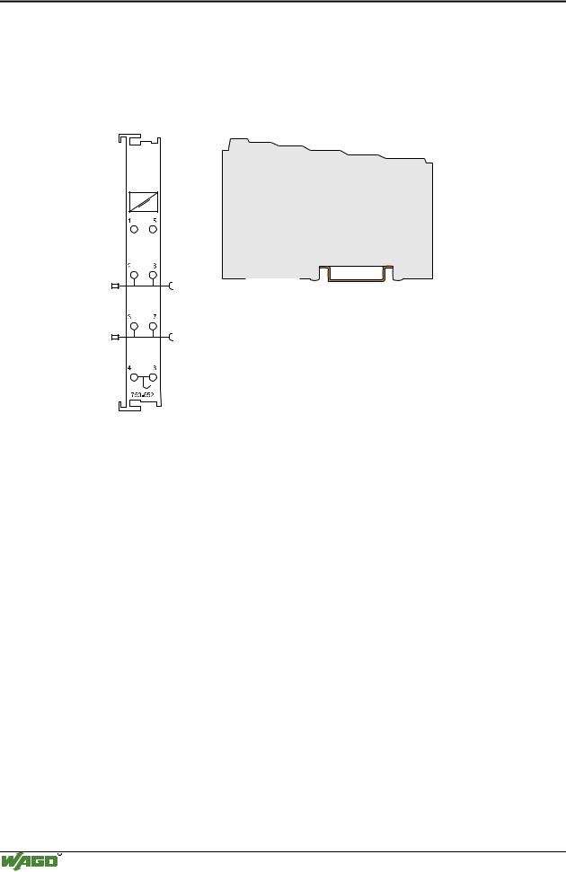
The grounding function increases the resistance against disturbances from electro-magnetic interferences. Some components in the I/O system have a carrier rail contact that dissipates electro-magnetic disturbances to the carrier rail.
|
|
|
|
|
|
|
|
|
|
|
|
|
|
|
|
|
|
|
|
|
|
|
|
|
|
|
|
|
|
|
|
|
|
|
|
|
|
|
|
|
|
|
|
|
|
|
|
|
|
|
|
|
|
|
|
|
|
|
|
|
|
|
|
|
|
|
|
|
|
|
|
|
|
|
|
|
|
|
|
|
|
|
|
|
|
|
|
|
|
|
|
|
|
|
|
|
|
|
|
|
|
|
|
|
|
|
|
|
|
|
|
|
|
|
|
|
|
|
|
|
|
|
|
|
|
|
|
|
|
|
|
|
|
|
Fig. 2-23: Carrier rail contact |
|
|
g0xxx10e |
|||||||||||
Attention
Care must be taken to ensure the direct electrical connection between the carrier rail contact and the carrier rail.
The carrier rail must be grounded.
For information on carrier rail properties, please see chapter 2.6.3.2.
WAGO-I/O-SYSTEM 750
CANopen
The WAGO-I/O-SYSTEM 750 • 35
Grounding
2.8.3 Grounding Protection
For the field side, the ground wire is connected to the lowest connection terminals of the power supply module. The ground connection is then connected to the next module via the Power Jumper Contact (PJC). If the bus module has the lower power jumper contact, then the ground wire connection of the field devices can be directly connected to the lower connection terminals of the bus module.
Attention
Should the ground conductor connection of the power jumper contacts within the node become disrupted, e.g. due to a 4-channel bus terminal, the ground connection will need to be re-established.
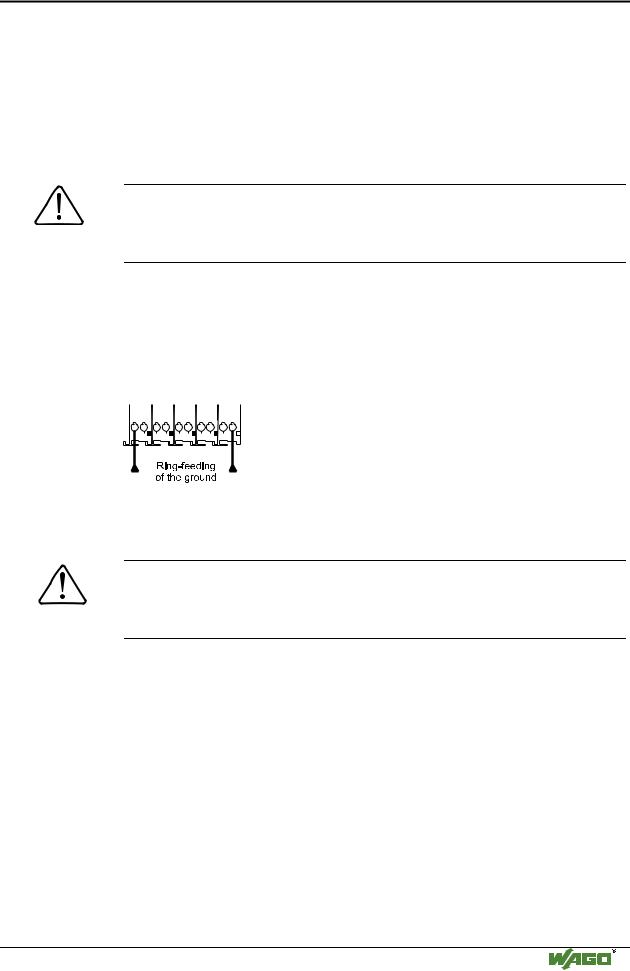
The ring feeding of the grounding potential will increase the system safety. When one bus module is removed from the group, the grounding connection will remain intact.
The ring feeding method has the grounding conductor connected to the beginning and end of each potential group.
|
|
|
|
|
|
|
|
|
|
|
|
|
|
|
|
|
|
|
|
|
|
|
|
|
|
Fig. 2-24: Ring-feeding |
g0xxx07e |
|||||||||||
Attention
The regulations relating to the place of assembly as well as the national regulations for maintenance and inspection of the grounding protection must be observed.
WAGO-I/O-SYSTEM 750
CANopen