Материал: m083700e
46• Fieldbus Controller 750-837, /02x-000, 750-838, /02x-000 Hardware
3.1.2.6 Configuration and programming interface
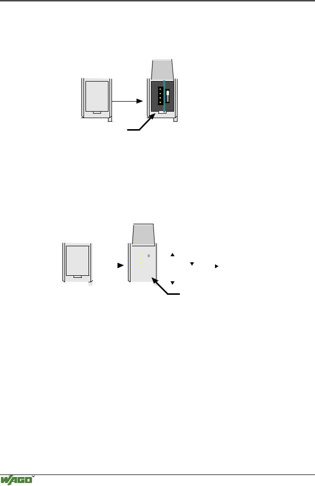
The configuration and programming interface is located behind the cover flap. This is used to communicate with WAGO-I/O-CHECK and for firmware transfer.
open flap
Configuration and programming interface
Fig. 3-6: Configuration and programming interface |
g01xx07e |
The communication cable (750-920) is connected to the 4 pole header.
3.1.2.7 Operating mode switch
The operating mode switch is located behind the cover flap beside the configuration and programming interface.
|
|
|
open |
|
|
|
|
|
|
|
|
|
|
|
||
|
|
|
|
|
|
|
|
|
|
|
|
|
|
|||
|
|
|
flap |
|
|
|
|
|
|
|
Run |
Stop |
Reset |
|||
|
|
|
|
|
|
|
|
|
|
|||||||
|
|
|
|
|
|
|
|
|
|
|||||||
|
|
|
|
|
|
|
|
|
||||||||
|
|
|
|
|
|
|
|
|
|
|
|
|
|
|
|
|
|
|
|
|
|
|
|
|
|
|
|
|
|
|
|
|
(pushing down) |
|
|
|
|
|
|
|
|
|
|
|
|
|
Update firmware |
|||
|
|
|
|
|
|
|
|
|
|
|
|
|
|
|||
|
|
|
|
|
|
|
|
|
|
|
|
|
|
|||
|
|
|
|
|
|
|
|
|
|
|
|
|
mode switch |
|||
|
|
|
|
|
|
|
|
|
|
|
|
|
||||
|
|
|
|
|
|
|
|
|
|
|
|
|
||||
Fig. 3-7: Operating mode switch |
|
|||||||||||||||
|
|
|
|
g01xx08e |
||||||||||||
The switch is a push/slide switch with 3 settings and a hold-to-run function.
Operating mode switch |
Function |
From middle to top position |
Activate program processing (RUN) |
|
|
From top to middle position |
Stop program processing (STOP) |
|
|
Lower position, bootstrap |
For original loading of firmware, |
|
not necessary for user |
|
|
Push down |
Hardware reset |
(i.e.with a screwdriver) |
All outputs are reset; variables are set to 0 or to FALSE |
|
or to an initial value. |
|
Retain variables or flags are not changed. |
|
The hardware reset can be performed with STOP as well |
|
as RUN in any position of the operating mode switch! |
|
|
An operating mode is internally changed at the end of a PLC cycle.
WAGO-I/O-SYSTEM 750
CANopen
Fieldbus Controller 750-837, /02x-000, 750-838, /02x-000 |
• 47 |
Hardware |
|
|
|
Attention
If outputs are set when switching over the operating mode switch from RUN to STOP, they remain set! Switching off the software side i.e. by initiators, are ineffective, because the program is no longer processed.
Note
With "GET_STOP_VALUE" (library "System.lib") WAGO-I/O-PRO CAA provides a function which serves to recognize the last cycle prior to a program stop giving the user the possibility to program the behavior of the controller in case of a STOP. With the aid of this function the controller outputs can be switched to a safe condition.
3.1.2.8 Hardware address (Module ID)
The DIP switch is used both for parameterizing the fieldbus coupler and for setting the module ID. This module ID is necessary for calculating the COB IDs (e.g. of PDO1...4, 1. Server SDO, etc.).
1
2
3
4
5
6
7
8
1 2 |
ON |
3 |
|
4 |
|
5 |
|
6 |
|
7 |
|
8 |
|
ON
Fig. 3-8: Setting of station (node) address |
g012440x |
The binary significance of the individual DIP switches increases according to the switch number, i.e. the module ID 1 is set by DIP1 = ON, the module ID 8 by DIP4 = ON, etc.
The nodes of the WAGO-I/O-SYSTEM can have module IDs from 1 to 127.
3.1.2.9 Setting the baud rate
The bus coupler supports 9 different Baud rates. DIP switches are used for setting.
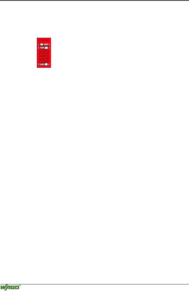
The bus coupler changes to the configuration mode using the set module ID = 0 (all DIP switches off) with subsequent power On. The currently set baud rate is displayed in this status. The baud rate display can be viewed by the top LED group (STOP, RUN, Tx-, Rx-Overflow), whereby STOP = Switch 1, RUN = Switch 2, Tx-Overflow = Switch 3 and Rx-Overflow = Switch 4. The currently set baud rate is displayed by the corresponding LEDs blinking slowly. Now the new baud rate can be set using the DIP switch, by switching the corresponding DIP switches to 'ON'.
The set configuration is saved by displacing DIP8 to ´on´. Following saving, the new baud rate is displayed by the corresponding LEDs having steady light.
WAGO-I/O-SYSTEM 750
CANopen
48• Fieldbus Controller 750-837, /02x-000, 750-838, /02x-000 Hardware
Exception: the baud rate of 1MBaud, this being displayed by all 4 LEDs blinking/being lit.
Example: |
125 kB: Tx-Overflow LED blink / are lit |
|
250 kB: STOP and RUN LED blink / are lit |
1


 ON
ON
2

3 |
4


5


6


7


8 |
Fig. 3-9: Example: Saving the baud rate 125 kB |
g012441x |
In this status no data exchange via CAN is possible.
DIP |
Function |
1 |
800 |
500 |
250 |
125 |
100 |
50 |
20 |
10 |
is displayed |
|
|
|
|
Mbit |
kB |
kB |
kB |
kB |
kB |
kB |
kB |
kB |
by LED |
1 |
(LSB) |
Baud rate |
0 |
1 |
0 |
1 |
0 |
1 |
0 |
1 |
0 |
STOP |
2 |
|
Baud rate |
0 |
0 |
1 |
1 |
0 |
0 |
1 |
1 |
0 |
RUN |
3 |
|
Baud rate |
0 |
0 |
0 |
0 |
1 |
1 |
1 |
1 |
0 |
Tx-Overflow |
4 |
(MSB) |
Baud rate |
0 |
0 |
0 |
0 |
0 |
0 |
0 |
0 |
1 |
Rx-Overflow |
5 |
|
|
|
|
|
|
|
|
|
|
|
|
6 |
|
|
|
|
|
|
|
|
|
|
|
|
7 |
|
|
|
|
|
|
|
|
|
|
|
|
8 |
|
Accept- |
´off´ -> |
´on´ : |
Accepting |
the |
configuration |
settings |
|
|
|
|
|
|
ance |
|
|
|
|
|
|
|
|
|
|
Once the baud rate setting / baud rate check is completed, switch off the operating voltage knowing that only the DIP value will be used to calculate the IDs which has been set during power ON. When switched off, the desired module ID (=1 as delivered) can be set on the DIP.
Default baud rate: 125 kB.
WAGO-I/O-SYSTEM 750
CANopen
Fieldbus Controller 750-837, /02x-000, 750-838, /02x-000 |
• 49 |
Operating system |
|
|
|
3.1.3 Operating system
3.1.3.1 Start-up
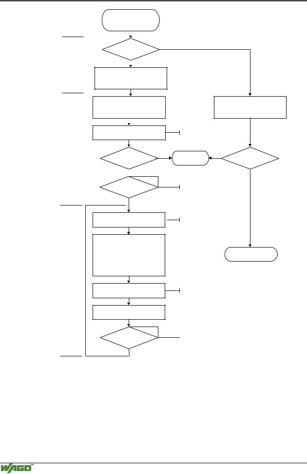
The controller starts-up after switching on the supply voltage or after a hardware reset. The PLC program in the flash memory is transferred to the RAM.
This is followed by the initialization of the system. The controller determines the I/O modules and the present configuration. The variables are set to 0 or to FALSE or to an initialization value given by the PLC program. The flags retain their status . The "I/O" LED blinks red during this phase.
Following an error free start-up, the controller changes over to the "RUN" mode. The "I/O" LED lights up green.
More Information
The evaluation of the displayed LED signals is described in Chapter 3.1.8 "LED Display"
A PLC program does not yet exist in the flash memory when delivered. The controller start-up is described without initializing the system. It then behaves as a coupler.
3.1.3.2 PLC cycle
The PLC cycle starts following an error free start-up when the operating mode switch is in the top position or by a start command from the WAGO-I/O-PRO CAA. The input and output data of the fieldbus and the I/O modules as well as the times are read. Subsequently the PLC program in the RAM is processed followed by the output data of the fieldbus and the I/O
modules in the process image. Operating system functions, amongst others, for diagnosis and communication are performed and the times are updated at the end of the PLC cycle. The cycle starts again with the reading in of the input and output data and the times.
The change of the operating mode (STOP/RUN) is made at the end of a PLC cycle.
The cycle time is the time from the start of the PLC program to the next start. If a loop is programmed within a PLC program, the PLC running time and thus the PLC cycle are extended correspondingly.
The inputs, outputs and times are not updated during the processing of the PLC program. This update occurs in a defined manner only at the end of the PLC program. For this reason it is not possible to wait for an event from the process or the elapse of a time within a loop.
WAGO-I/O-SYSTEM 750
CANopen
50• Fieldbus Controller 750-837, /02x-000, 750-838, /02x-000 Operating system
|
Switching on the |
|
|
|
supply voltage |
|
|
|
|
|
|
|
|
|
|
|
Is a PLC |
No |
|
|
program in the Flash |
||
|
|
||
“I/O” LED |
memory ? |
|
|
|
|
|
|
is blinking |
|
Yes |
|
orange
PLC program transfer from the flash memory to RAM
|
Determination of the I/O modules |
||
|
and the configuration |
|
|
|
|
|
|
|
|
|
|
|
Initialization |
|
|
|
of the system |
|
|
“I/O” LED |
|
|
|
is blinking |
|
|
|
red |
|
|
No |
|
Test o.k.? |
||
|
|
||
 Yes
Yes
STOP
Operating mode
 RUN
RUN
PLC cycle
Reading inputs, outputs and times
PLC program in the RAM is processed
“I/O” LED
is shining green
Writing outputs
Operating system functions, updating times
STOP
Operating mode
RUN
Fig. 3-10: Controller operating system
Determination of the I/O modules and the configuration
Variables are set to 0 or FALSE or to their initial value,
flags remain in the same status.
Stop |
No |
Test o.k.? |
|
Yes
operating mode switch is in the top position or start command in WAGO-IO-PRO 32:
Online/Start or Online/Stop
Fieldbus data,
data of I/O modules
Fieldbus start behaviour as a coupler
Fieldbus data,
data of I/O modules
operating mode switch is in the top position or  start command in WAGO-IO-PRO 32:
Online/Start or Online/Stop
g012x41x
WAGO-I/O-SYSTEM 750
CANopen