Материал: m083700e

Внимание! Если размещение файла нарушает Ваши авторские права, то обязательно сообщите нам

166 • CANopen

Network Communication

Example:

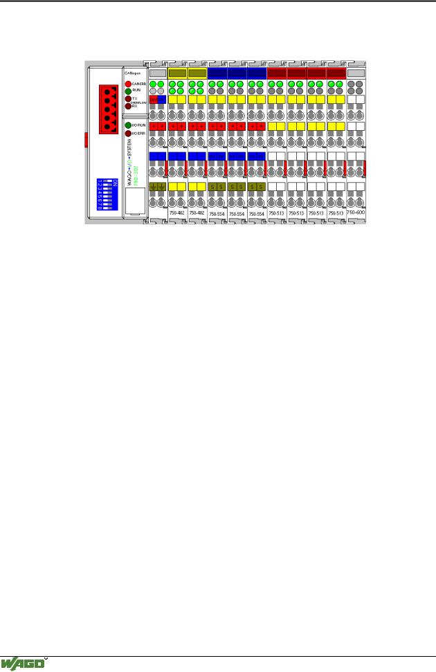
A coupler of the following configuration is projected:

Kl.1 Kl.2 Kl.3 Kl.4 Kl.5 Kl.6 Kl.7 Kl.8 Kl.9

Configuration for the full version:


Sub-


Value


Meaning


Index


0


0x09


Total number of connected (9) and virtual (0) modules


1


0x8063


digital, input, 4 channels, 1bit per channel, connected (mod. 1)


2


0x8063


digital, input, 4 channels, 1bit per channel, connected (mod. 2)


3


0x 8094


analog, output, 2 channels, 2byte per channel, connected (mod. 3)


4


0x 8094


analog, output, 2 channels, 2byte per channel, connected (mod. 4)


5


0x 8094


analog, output, 2 channels, 2byte per channel, connected (mod. 5)


6


0x 8055


digital, output, 2 channels, 1bit per channel, connected (mod. 6)


7


0x 8055


digital, output, 2 channels, 1bit per channel, connected (mod. 7)


8


0x 8055


digital, output, 2 channels, 1bit per channel, connected (mod. 8)


9


0x 8055


digital, output, 2 channels, 1bit per channel, connected (mod. 9)


WAGO-I/O-SYSTEM 750

CANopen

CANopen • 167

Network Communication

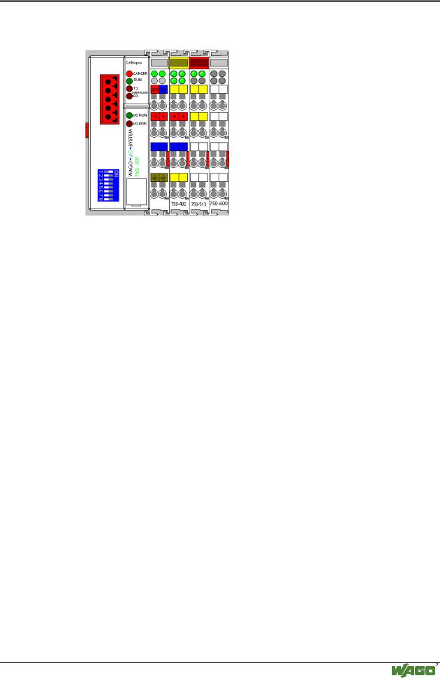
As a second step, a coupler is protected which is a sub-quantity of the first one. The only modules used are module 2 and 8.

Kl.2 Kl.8

Configuration for the version mod. 2 and mod. 8 connected:

S-Idx.

Value

Meaning

0

0x09

Total number of connected (2) and virtual (7) modules


1

0x0063

digital, input, 4 channels, 1bit per channel, not conn.(mod. 1)


2

0x8063

digital, input, 4 channels, 1bit per channel, connected (mod. 2)


3

0x 0094

analog, output, 2 channels, 2byte per channel, not conn.(mod. 3)


4

0x 0094

analog, output, 2 channels, 2byte per channel, not conn.(mod. 4)


5

0x 0094

analog, output, 2 channels, 2byte per channel, not conn.(mod. 5)


6

0x 0055

digital, output, 2 channels, 1bit per channel, not conn.(mod. 6)


7

0x 0055

digital, output, 2 channels, 1bit per channel, not conn.(mod. 7)


8

0x 8055

digital, output, 2 channels, 1bit per channel, connected (mod. 8)


9

0x 0055

digital, output, 2 channels, 1bit per channel, not conn.(mod. 9)


With regard to their entries in the object directory (connected modules), the behavior of both couplers is identical. Consequently, their behavior is also identical during PDO mapping.

Bit 4 must be set in index 0x6200, sub-index 1, for instance, to be able to set the 1st channel of the output module 8 (750-513).

This process is identical for both configurations.

If there was not an empty module configuration, in contrast to the above, bit 0 would have to be set for the 2nd configuration, index 0x6200, sub-index 1, in order to set the same output channel.

WAGO-I/O-SYSTEM 750

CANopen

168 • CANopen

Network Communication

5.3.4.3.22Object 0x5000, Read Input Process Image


Idx


S-Idx


Name


Type


Attribute


Default Value


Meaning


0x5000


0


number of input byte


Unsigned16


RO


-


Number of relevant bytes in input PA


1


input segment 1


Octed_String


RO


-


1. Input PA segment (the bottom 255


bytes of 512 bytes PA)


2


input segment 2


Octed_String


RO


-


2. Input PA segment (the top 255 bytes of


512 bytes PA. Is only available, if > 255


bytes input data)


Permits reading of the entire input process image as a domain via SDO, allowing access to all input data „as a block“.

Note

The access via SDO being slow, we recommend transmitting time critical data only via PDO.

5.3.4.3.23Object 0x5001, Write Output Process Image

Idx

S-Idx

Name

Type

Attribute

Default Value

Meaning

0x5001

0

number of output byte

Unsigned16

RO

none

Number of relevant bytes in output PI


1

input segment 1

Octed_String

RW

none

1. Output PA segment (the bottom 255


bytes of 512 bytes PA)


2

input segment 2

Octed_String

RW

none

2. Output PA segment (the top 255 bytes


of 512 bytes PA. Is only available, if >


255 bytes output data are possible accord-


ing to the module configuration)

Permits writing of the entire output process image as a domain via SDO „as a block“.

Note

The access via SDO being slow, we recommend transmitting time critical data only via PDO.

5.3.4.3.24Object 0x5200, Controller Configuration Object

Idx

S-Idx

Name

Type

Attribute

Default Value

Meaning

0x5200

0

max. supported Subin-

Unsigned8

RO

-

Maximally supported Subindex


dex


1

PDO processing

Unsigned8

RW

0

specifies the processing of the received


PDOs.


0: Logical data output, that means as


soon as a PDO arrived doubly, an


internal bus cycle starts.


1: Data of the last PDO win.


2

Deactivate blink display

Unsigned8

RW

0

activates/deactives the display of the


Warning Level


Warning Level


0: The display of Warning Level is


activated


1: The display of Warning Level is


deactivated


3

Deactivate global

Unsigned8

RW

0

activates/deactivates the transmission of


module diagnostics via


global module diagnostics via Emergency


Emergency messages


messages


0: dispatch diagnostic messages


1: do not dispatch diagostic messages

WAGO-I/O-SYSTEM 750

CANopen

CANopen • 169

Network Communication

5.3.4.3.25Object 0x5201, Diagnostics Configuration Object

Idx

S-Idx

Name

Type

Attribute

Default Value

Meaning

0x5200

0

max. supported Sub

Unsigned8

RO

-

Maximally supported Subindex = Num-


index = Number of


ber of modules


modules


1

Diagnostics behavior of

Unsigned8

RW

0

Each bit within the byte represents a


the 1st put module


channel of the module (bit 0 channel 0,


bit 1 channel 1..., bit 7 channel 7)


Bit n = 1: no diagnostics messages are


transmitted via Emergency


(n=0...7)


If all bits are set to 1 (255)


the transmission of the diagnostics mes-


sages via Emergency is deactivated for


this module, independently of the channel


number of the module.


….


....


64

Diagnostics behavior of

Unsigned8

RW

0

Each bit within the byte represents a


the 64th put module


channel of the module (bit 0 channel 0,


bit 1 channel 1..., bit 7 channel 7)


Bit n = 1: no diagnostics messages are


transmitted via Emergency


(n=0...7)


If all bits are set to 1 (255)


the transmission of the diagnostics mes-


sages via Emergency is deactivated for


this module, independently of the channel


number of the module.

WAGO-I/O-SYSTEM 750

CANopen

170 • CANopen

Network Communication

5.3.4.4 Standard Device Profile Area – DS 401

The controller supports the standard device profile Device Profile for Generic I/O Modules.

The following table shows all objects of the standard profile DS401 supported by the fieldbus controller.

Idx

Name

Type

Meaning

See on


page

0x6000

Read Input 8 Bit

Array Unsigned8

Data of digital input I/O modules

171

0x6005

Global Interrupt Enable Digital 8-

Unsigned8

Global release of the transmission of 8

171


Bit


bit digital input data


0x6006

Interrupt Mask Any Change 8-Bit

Array Unsigned8

Release of the transmission with each

171


change of 8 bit digital input data


0x6007

Interrupt Mask Low-to-High 8-

Array Unsigned8

Release of the transmission if a posi-

171


Bit


tive flank of 8 bit digital input data


occurs


0x6008

Interrupt Mask High-to-Low 8-

Array Unsigned8

Release of the transmission of a

172


Bit


negative flank of 8 bit digital input


data


0x6200

Write Output 8-Bit

Array Unsigned8

Data of digital output I/O modules

172

0x6206

Error Mode Output 8-Bit

Array Unsigned8

Release of pre-defined error values of

172


the 8 bit digital output data


0x6207

Error Value Output 8-Bit

Array Unsigned8

Pre-defined error values of the 8 bit

173


digital output data


0x6401

Read Analog Input 16-Bit

Array Unsigned16

Data of analog input I/O modules

173


(16 bit)


0x6411

Write Analog Output 16-Bit

Array Unsigned16

Data of analog output I/O modules

173


(16 bit)


0x6421

Analog Input Trigger Selection

Array Unsigned8

Determination of trigger condition for

174


16 bit analog input data


0x6423

Analog Input Global Interrupt

Boolean

Global release of the transmission of

175


Enable


16 bit analog input data


0x6424

Analog Input Interrupt Upper

Array Unsigned16

Transmission of 16 bit input data if

175


Limit Integer


threshold value exceeded


0x6425

Analog Input Interrupt Lower

Array Unsigned16

Transmission of 16 bit input data if

175


Limit Integer


threshold value exceeded


0x6426

Analog Input Interrupt Delta

Array Unsigned16

Transmission if the 16 bit input data

175


Unsigned


have changed at least by the delta


value


0x6427

Analog Input Interrupt Negative

Array Unsigned16

Transmission if the 16 bit input data

176


Delta Unsigned


have reduced at least by the delta


value


0x6428

Analog Input Interrupt Positive

Array Unsigned16

Transmission if the 16 bit input data

175


Delta Unsigned


have increased at least by the delta


value


0x6443

Analog Output Error Mode

Array Unsigned8

Release of pre-defined error values of

176


the 16 bit output data


0x6444

Analog Output Error Value

Array Unsigned16

Value in the event of an error of the

177


Integer


16 bit output data


0x67FE

Error Behavior

Array Unsigned8

Status change in the event of an error

177

WAGO-I/O-SYSTEM 750

CANopen

Источник: https://studfile.net/preview/16369781/