Материал: m083700e

Внимание! Если размещение файла нарушает Ваши авторские права, то обязательно сообщите нам

CANopen • 171

Network Communication

5.3.4.4.1 Object 0x6000, Digital Inputs


Idx


S-Idx


Name


Type


Attribute


Default Value


0x6000


0


Number of digital input blocks


Unsigned8


RO


-


1


1. input block


Unsigned8


RO


-


2


2. input block


Unsigned8


RO


-


....


....


....


....


....


32


32. input block


Unsigned8


RO


-


This object contains the process data of the digital input modules. Sub-index 1 contains the first 8 digital input channels from the left to the right, counted from starting with the bus coupler. Sub-index 2 the next etc.

5.3.4.4.2 Object 0x6005, Global Interrupt Enable Digital 8-Bit

Idx

S-Idx

Name

Type

Attribute

Default Value

0x6005

0

Global Interrupt Enable Digital 8-Bit

Unsigned8

RW

1

With this object, the transmission of the digital input data is controlled using PDO. If the value is 1, the transmission is generally released, only depending on the objects 0x6006...0x6008 and the type of transmission of the PDO. If the value is 0, the digital input data is not transmitted, independent of the objects 0x6006...0x6008.

5.3.4.4.3 Object 0x6006, Interrupt Mask Any Change 8-Bit

Idx

S-Idx

Name

Type

Attribute

Default Value

0x6006

0

Number of digital input blocks

Unsigned8

RO

-


1

Mask 1. input block

Unsigned8

RW

255


2

Mask 2. input block

Unsigned8

RW

255


....

....

....

....

....


32

Mask 32. input block

Unsigned8

RW

255

This object is used to define the digital input channel, which will send its data in the event of a change. Prerequisite being that transmission is generally released (Object 0x6005 = 1).

0 = Transmission blocked in the event of a change (per channel) 1 = Transmission released in the event of a change (per channel)

Example:

Sub-Index 0 = 1, Sub-Index 1 = 65 = 0x41


only channel 1 and 7 will transmit their data in the event of a


change

5.3.4.4.4 Object 0x6007, Interrupt Mask Low-to-High 8-Bit

Idx

S-Idx

Name

Type

Attribute

Default Value

0x6007

0

Number of digital input blocks

Unsigned8

RO

-


1

Mask 1. input block

Unsigned8

RW

0


2

Mask 2. input block

Unsigned8

RW

0


....

....

....

....

....


32

Mask 32. input block

Unsigned8

RW

0

This object is used to define the digital input channel, which will send its data in the event of a positive flank (change from 0 to 1). Prerequisite being that the transmission is generally released (Object 0x6005 = 1). This object has an OR link to object 0x6006.

WAGO-I/O-SYSTEM 750

CANopen

172 • CANopen

Network Communication

0 = Transmission blocked with a positive flank (per channel) 1 = Transmission release with a positive flank (per channel)

Example:

Index 0x6006 Sub-Index 0

= 1, Sub-Index 1 = 65 = 0x41


Index 0x6007 Sub-Index 0

= 1 Sub-Index 1 = 33 =0x21

Channels 1 and 7 always transmit their data in the event of a change

Channel 6 is only transmitted with a positive flank

5.3.4.4.5 Object 0x6008, Interrupt Mask High-to-Low 8-Bit


Idx


S-Idx


Name


Type


Attribute


Default Value


0x6008


0


Number of digital input blocks


Unsigned8


RO


-


1


Mask 1. input block


Unsigned8


RW


0


2


Mask 2. input block


Unsigned8


RW


0


....


....


....


....


....


32


Mask 32. input block


Unsigned8


RW


0


This object is used to define the digital input channel, which transmits its data in the event of a negative flank (change from 1 to 0). Prerequisite being that the transmission is generally released (Object 0x6005 = 1). This object has an OR link to object 0x6006.

0 = Transmission blocked with a negative flank (per channel) 1 = Transmission released with a negative flank (per channel)

Example:

Index 0x6006 Sub-Index 0

= 1, Sub-Index 1 = 65 = 0x41


Index 0x6008 Sub-Index 0

= 1 Sub-Index 1 = 33 =0x21

Channels 1 and 7 always transmit their data in the event of a change

Channel 6 is only transmitted with a negative flank

5.3.4.4.6 Object 0x6200, Digital Outputs

Idx

S-Idx

Name

Type

Attribute

Default Value

0x6200

0

Number of digital output blocks

Unsigned8

RO

-


1

1. output block

Unsigned8

RW

0


2

2. output block

Unsigned8

RW

0


....

....

....

....

....


32

32. output block

Unsigned8

RW

0

This object contains the process data of the digital output modules. Sub-index 1 contains the first 8 digital output channels from left to right, counting starting from the bus coupler. Sub-index 2 the next etc.

WAGO-I/O-SYSTEM 750

CANopen

CANopen • 173

Network Communication

5.3.4.4.7 Object 0x6206, Error Mode Output 8-Bit


Idx


S-Idx


Name


Type


Attribute


Default Value


0x6206


0


Number of digital output blocks


Unsigned8


RO


-


1


Mask 1. output block


Unsigned8


RW


255


2


Mask 2. output block


Unsigned8


RW


255


....


....


....


....


....


32


Mask 32. output block


Unsigned8


RW


255


This object defines whether the outputs change to a pre-defined error status in the event of an error (i.e. bus coupler changes to the Stopped status, Nodeguarding has failed,...) (see object 0x6207). If the error is remedied, the outputs remain in their momentary status, i.e. the set error status of the output channels remains unchanged.

0 = Outputs remain unchanged (per channel)

1 = Outputs change to a pre-defined error status (per channel)

5.3.4.4.8 Object 0x6207, Error Value Output 8-Bit

Idx

S-Idx

Name

Type

Attribute

Default Value

0x6207

0

Number of digital output blocks

Unsigned8

RO

-


1

Mask 1. output block

Unsigned8

RW

0


2

Mask 2. output block

Unsigned8

RW

0


....

....

....

....

....


32

Mask 32. output block

Unsigned8

RW

0

This object is used to define the values, which the outputs should assume in the event of an error. Prerequisite being that the corresponding bit in object 0x6206 is set.

0 = Output to 0 (per channel)

1 = Output to 1 (per channel)

Example:

Index 0x6206 sub-index 0

= 1, sub-index 1 = 65 = 0x41


Index 0x6207 sub-index 0

= 1 sub-index 1 = 33 = 0x21

Channel 1 is set to 1, channel 7 is set to 0,

all other output channels remain unchanged in the event of an error

5.3.4.4.9 Object 0x6401, Analog Inputs 16 Bit

Idx

S-Idx

Name

Type

Attribute

Default Value

0x6401

0

Number analog input channels

Unsigned8

RO

-


(16Bit)


1

1. channel

Unsigned16

RO

-


....

....

....

....

....


254

254. channel

Unsigned16

RO

-

This object contains the process data of the analog input modules. Sub-index 1 contains the first analog input channel from left to right, counting starting with the bus coupler. Sub-index 2 the second, etc.

WAGO-I/O-SYSTEM 750

CANopen

174 • CANopen

Network Communication

5.3.4.4.10Object 0x6411, Analog Outputs 16 Bit

Idx

S-Idx

Name

Type

Attribute

Default Value

0x6411

0

Number analog input channels

Unsigned8

RO

-


(16Bit)


1

1. channel

Unsigned16

RW

0


....

....

....

....

....


254

254. channel

Unsigned16

RW

0

This object contains the process data of the analog output modules. Sub-index 1 contains the first analog output channel from left to right, counting starting with the bus coupler. Sub-index 2 the second, etc.

5.3.4.4.11Object 0x6421, Analog Input Interrupt Trigger Selection

Idx

S-Idx

Name

Type

Attribute

Default Value

0x6421

0

Number analog input channels

Unsigned8

RO

-


(16Bit)


1

Trigger 1. channel

Unsigned8

RW

7


....

....

....

....

....


128

Trigger 128. channel

Unsigned8

RW

7

This object is used to define the condition of the transmission. Prerequisite for the transmission being that a 1 is entered in object 0x6423, and consequently the general transmission released.

Design Sub-Index 1..128:

Bit

Transmission conditions

Configuration


Sub-Index

0

Threshold value exceeded

0x6424


1

Threshold value fallen short

0x6425


2

Change of the input value exceeding the delta value for

0x6426


the last transmission


3

Reduction of the input value by more than the delta value

0x6427


for the last transmission


4

Increase of the input value by more than the delta value

0x6428


for the last transmission


5 to 7

Reserved

-


5.3.4.4.12Object 0x6423, Analog Input Global Interrupt Enable

Idx

S-Idx

Name

Type

Attribute

Default Value

0x6423

0

Global Interrupt Enable Analog

Unsigned8

RW

0


16Bit


This object is used to control the transmission of the analog input data using PDO. If the value is 1, the transmission is released, and it only depends on object 0x6421 and the transmission type of the PDO. If the value is 0, no transmission of the analog input data is made, independent of object 0x6421.

Attention

In the default setting, the transmission of analog input data is deactivated.

WAGO-I/O-SYSTEM 750

CANopen

CANopen • 175

Network Communication

5.3.4.4.13Object 0x6424, Analog Input Interrupt Upper Limit Integer


Idx


S-Idx


Name


Type


Attribute


Default Value


0x6424


0


Number analog input channels


Unsigned8


RO


-


(16Bit)


1


Upper Limit 1. channel


Unsigned16


RW


0


....


....


....


....


....


128


Upper Limit 128. channel


Unsigned16


RW


0


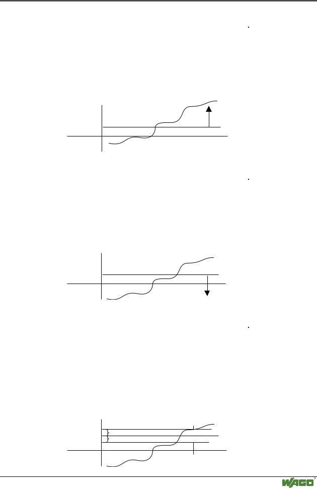
This object allows a threshold value monitoring if it is configured in object 0x6423. If the input value is the defined threshold value, no transmission will take place until a further trigger condition is set (i.e. object 0x6426).

Transmission

Threshold value

g012435e

5.3.4.4.14Object 0x6425, Analog Input Interrupt Lower Limit Integer

Idx

S-Idx

Name

Type

Attribute

Default Value

0x6425

0

Number analog input channels

Unsigned8

RO

-


(16Bit)


1

Lower Limit 1. channel

Unsigned16

RW

0


....

....

....

....

....


128

Lower Limit 128. channel

Unsigned16

RW

0

This object allows a threshold value monitoring if it is configured in object 0x6423. If the input value is the determined threshold value, transmission will take place until a further trigger condition is set (i.e. object 0x6426).

Threshold value

Transmission

g012436e

5.3.4.4.15Object 0x6426, Analog Input Interrupt Delta Unsigned

Idx

S-Idx

Name

Type

Attribute

Default Value

0x6426

0

Number analog input channels

Unsigned8

RO

-


(16Bit)


1

Delta value 1. channel

Unsigned16

RW

0


....

....

....

....

....


128

Delta value 128. channel

Unsigned16

RW

0

The new value to be transmitted must, by definition of this object, be larger by at least the delta value or smaller than the value sent before.

This object, for instance, can be linked with the object 0x6424, so that the transmission will only be completed when the set threshold value and also the delta function are fulfilled.

Transmission

Previous value

Delta

Delta


Transmission

g012437e

WAGO-I/O-SYSTEM 750

CANopen

Источник: https://studfile.net/preview/16369781/