Материал: chapter V
5.4 Films and plates recording
5.4.1 General characteristics
Illustrative transparencies were initially output in the recording sections of apparatuses called “color” scanners in accordance with the most important reproduction function which determined their wide use in printing practice [1.3; 1.10].
Later, in the mid-1970s, monochrome electronic devices, such as the Autocon 1000 of ECRM, appeared. They replaced b/w photomechanical reproduction, primarily in newspaper production. Halftones of CT originals were recorded at a given scale with the necessary sharpness and tone correction not only on the film, but also on photo paper. In combination with actively developed by the time the phototypesetting it had facilitated manual stripping of text-picture pages. The image could be positive, which, in contrast to the use of cameras, provided a double saving of expensive film in relation to the most common copying on positively sensitive litho plates [5.23].
As the integration processing of the text and illustrations the electronic phototypesetters and scanner recording sections were replaced by the universal film output device - imagesetter. Scanner in prepress began to be called only the device of image capturing, borrowing for this purpose the term used earlier for the corresponding peripheral device of computer technology. As coming further to computer-to-plate (CtP) concept the term “imagesetter” had, in turn, transformed to “platesetter”.
The main characteristics of recording devices are:
format and dimensional accuracy of recorded matter;
resolution;
- performance;
- type of light source used;
- precision stacking of the recorded lines and stability of exposure.
The large format allows for reproducing big-size calendars and posters while for particularly small products (playing cards, labels, postcards, etc.), the image is possible to obtain repeatedly over the entire press sheet. This excludes additional operations, costs and quality losses associated with the images multiplication in special equipment (see Fig. 4.7).
As the growth performance and the functionality of raster processors the large output format allowed for the recording in a press sheet size along with the register marks, test wedges and other proprietary information.
In addition to eliminating manual assembly of mechanicals the electronic imposition freed also from the necessity of scanning the plates prior their installation in the press. Previously, this was done on special auxiliary equipment to obtain information about the ink supply along the print sheet zones of its adjustment. Pre - installation of such adjustment significantly reduces the time and waste of paper in the “print-ready” process. With the electronic imposition, these data are already available in digital files, which structure is consistent in this regard with the parameters of various types of presses in the concept of CIP3 (Computer Integrated Prepress, Press, Postpress).
Speed of recording determines the performance and thus, to a large extent, the profitability of this expensive equipment. Resolution defines the quality of tone and color rendition as well as the available screen frequency. These device parameters and the characteristics of used materials depend in turn on the irradiation source properties.
However, the most characteristic common feature, which largely determines most of the above parameters, is the principle of construction of the output device. In this sense, there are distinguished the devices:
- fed from roll of material (capstan);
- with mounting the recorded substrate on the drum (on-drum);
- with fixing the substrate inside the drum or some caved surface (in-drum).
5.4.2 Capstan devices
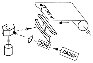
In devices of this type (Figure 5.10) slow scan is carried out by pulling a film or photo paper from the roll feed cassette through the exposure area to the developing machine. The line scan is provided by the laser beam move by a mirror. The advantage of this type of devices is in their low cost and high degree of automation of loading and extraction of exposed material. At the same time, they are characterized by relatively low resolution, format, accuracy and repeatability of the output pages. Despite the complex optical system, the exposure aperture was limited to 25 microns, and the output image width rarely exceeded 400 mm.
|
Figure 5.10 Output roll fed device with the recording beam deflection by a multi-faceted mirror Resolution of the order of 1000 dpi (40 lines/mm) and other parameters of such scanning devices had fully met the requirements of the electronic phototypesetting and facsimile transmission of newspapers, however, were insufficient to output the integrated, in particular color layouts in computer publishing systems. To this end, technical solutions were found that allowed to increase the accuracy of the film transportation, reduce the deviation of the page sizes to 0.015 mm and increase the accuracy of the exposure beam positioning. The principal improvement was achieved with the laser displacement by LEDs line array. Similarly the use of multiple ink nozzle arrays allowed for creating large format plotters. To provide an acceptably imperceptible, sufficiently high screen frequency, the discussed above solutions were used.
|
5.4.3 On-drum and in-drum recording
The output section of the on-drum type is traditionally inherent in the color scanners. The maximum format of output reached 750 x 1100 mm with the accuracy of the separations size repeatability of ±0,005 mm. The use of argon-ion lasers with the relatively short-wave radiation and short – focus lenses allowed for obtaining a recording spot of 5~10 microns and, respectively, the resolution up to 5000 dpi (200 lines/mm).
Their relative disadvantage was in the complexity of film loading and removal. These operations were carried out manually or semi-automatically in non-actinic ambient light. Scanner manufacturers have tried different ways to cope with this kind of inconvenience. So, in Chromograph 296 the drum with a fixed over it film was in a removable light-proof cassette, while in Chromograph 300/350 there was used a flat cassette from which a sheet of film format 400 x 500 mm automatically transferred to the cylinder and fed back to the cassette after recording. All this did not eliminate the additional manual operations of charging and removing the film from the cassette in the dark room. The use of cassettes proved to be unpromising in terms of increasing the scanner basic parameter— the recording format. Later, the output sections of the on-drum scanners became remotely controlled modules placed in a dark room.
With the format growth, not only the drum dimensions but also its mass increase. At the same time, maintaining the performance at the same resolution, i.e. the number of recorded lines per unit drum length requires increasing the speed of rotation. It, in turn, had increased the dynamic loads, the drive power for fast acceleration and created the problems with holding the film by a vacuum suction.
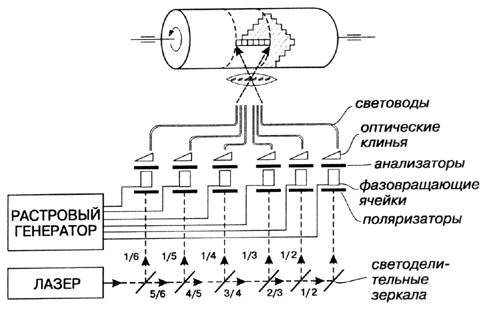
Therefore, the required performance at a technically acceptable speed of rotation of about 1000 -1200 rpm is provided by simultaneous recording of several (6 -10) independently controlled exposing spots. To this end, the laser beam is split [5.24] in the beam-splitting system (Figure 5.11) or in an acousto-optic deflector [5.25]. Even more lines are exposed in parallel, when instead of a laser the line of LEDs is used, installed in the recording head parallel to a certain segment of the drum or along the entire its length.
|
|
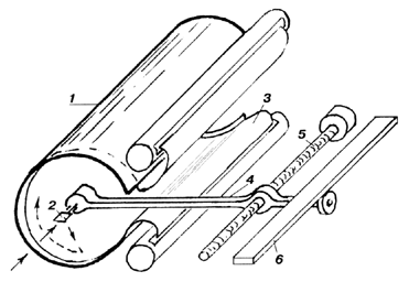
Figure 5.11 The splitting of the laser beam by semi-transparent mirrors and parallel recording of multiple lines allow for reduce the speed of the drum rotation Compared to the trivial line-by-line scan, parallel exposure systems require some extraordinary output data organization in the RIP. In in-drum systems, a line scan is provided inside the cylindrical chamber (1) by rotating the mirror (2) tilted to its axis at an angle of 450 (Figure 5.12). To reduce the influence of rotation eccentricity on the beam path, the mirror was subsequently replaced by a prism. The camera has a longitudinal recess required for film (3) loading and moving the mirror bracket (4). Therefore, the length of the recorded line is not equal to the entire camera circumference and is limited only by its part — arc. This, apparently, explains the name “arc” scanning system, adopted in the Russian literature of the 70s when on this principle the equipment Gazeta-2 of newspapers photo facsimile transfer for the remote, decentralized printing was created [5.26]. In this equipment, the photographic material was not only automatically cut off from the roll, inserted into the camera and clung to its inner surface, but also output after recording directly into the developing machine. Slow scan was provided by moving the camera in the longitudinal direction. In the later imagesetters and CtP devices of this type, camera is usually stationary, and the entire mechanism of the slow scan moves inside it (Figure 5.12). The bracket (4) to this mechanism is rigidly connected via the longitudinal recess of the chamber to the external feed drive, lead screw (5) and guides (6). |
|
Figure 5.12 Scan image inside a cylindrical camera by rotating mirror or prism Here, unlike on-drum systems, there is no need to turn off the line scan to remove or install the recorded material. This was especially effective for analog photo-facsimile newspapers transmission, because it had eliminated the loss of time on phasing the scan lines of the receiver and transmitter prior to the next page transmission. The relatively small mass of the mirror or prism allows for increase the line scan frequency to tens of thousands of rpm and thus provide high performance in the usual (line-by-line) organization of data controlling the exposing beam.
|
5.4.4 “Hard” and “soft” dots
“Soft” or to some extent un-sharp dots, inherent in mechanicals, allowed, as was shown in figure 4.6, for the manual tone and color correction by halftone dots etching on a film. Such a facility was lost, as coming to Electronic Dot Generation (EDG), on behalf of providing the rigid connection between the image signal and resulting print tone value.3 Degree of dot “hardness” is defined in this sense according to the tolerances in the process of copying the halftone transparency on, for example, litho plate. The explained below empirical requirements to dot parameters were in this light given in 1990ies by ISO 12647.
Film based plate making is nowadays greatly replaced by the direct CtP techniques. Nevertheless such explanation isn’t out of place due to the similar development tolerances effect on the interaction of toner with un-sharp energy distribution in a latent dot image on OPC. Similar effects are also met because of non-uniform heat distribution in thermal exposing the plate layers by laser in CtP.
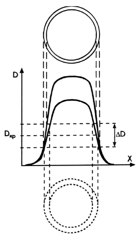
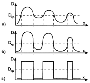
The dot sharpness depends on film properties, specifics of screening process (projection, contact, electronic), light scattering in the film layer and other factors. Figure 5.13 shows the examples of optical density distributions in projection (a) and electronic (b) screening, as well as the ideal П-shaped ones (c).
In these graphs Dthr – threshold density as a certain utmost value at which the radiation transmitted through the transparency is still sufficient to dampen the plate sensitive layer. For mechanicals, with respect to a litho plate making Dthr = 1.0 ± 0.2. Higher exposures were unacceptable, because, as follows from figure 5.13 (a), of the loss of small dots and, accordingly, highlight gradations. Conversely, excessive reduction of exposure, as can be seen from the same figure, was fraught with the loss of small gaps in the shadows.
|
Figure 5.13 Approximate density distributions within halftone dots for the photomechanical (a) and electronic (b) screening; with the ideal properties (c) |
The instability of the copy density can be caused by the deviations of plate sensitivity, exposure, conditions of development and other reasons. A means of controlling the magnitude and stability of exposure is the stepwise continuous tone test of 13 patches, differing by approximately 0.15 density units (at the left in figure 5.14).

Figure 5.14Test for the control of copying a halftone transparency onto a sensitized litho plate
The exposure value is set from the condition of optimal use the plate resolution. To do this, the test also contains a pairs of positive and negative concentric rings of different frequency. The exposure, in which both positive and negative rings of the highest frequency are equally clear, is considered optimal. Deviation from this value in a larger direction leads to a decrease or complete loss of thin elements on a white background due to lateral light scattering within a plate sensitive layer. On the other hand, the lower exposure entails a reduction or non-processing of small gaps that have a greater density on the film, compared with larger ones (Figure 5.13). After finding the optimal mode by trial copying with different exposures, the current control is carried out according to the number of the first stepwise scale patch worked in this mode.
Even with relatively high sharpness, the density, especially for small dots and gaps, on the transparencies obtained in different output devices, can differ significantly. In this regard, the exposure may require some adjustment when changing their type.
Lateral light scattering in the copying layer reduces the size of printed elements on the plate by 2 - 4%. This "negative" dot gain together with its other components (optical and physical) is taken into account and compensated at the prepress stage.
The objective criterion for the copying properties can serve as shown in Figure 5.15, the gradient of density on the front of distribution at level Dthr:
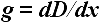 5.5
5.5
Its required value can be calculated from the permissible deviations of achromatic or color tone values of the halftone print through the corresponding changes in the dot areas.
|
Figure 5.15 The higher the dot densitogram gradient at Dthr level (a), the less deviations of the printing element size on the plate (b) within the tolerance for the copying process stability
|
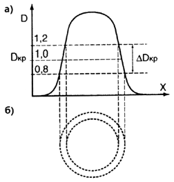
At the same steepness of a distribution front the copying instability more significantly impacts on the small dots area. Therefore, the requirements to dot sharpness become tougher with increasing the regular halftones ruling, as well as with stochastic screening for its fine dots are involved in the gradation transfer across the whole tone range.
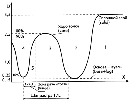
Transparency parameters, set out in the first and second ISO 12647 versions [2.8; 2.9; 3.19] illustrates the graph in figure 5.16. It shows the advised densities of fog+base, solids, dots and gaps.
To avoid the plate "shading", the open areas density is limited to 0.15, and the gaps between the dots to 0.25. As can be seen from the same graph, the standard assumes that if the density in the solid area reaches 3.5 units, then in the “core density” within dot it will be at least 2.5, and in small ones it will reliably exceed the threshold. These recommendations are based on the properties of transparencies, which were obtained in the past by means of projection or contact Halftoning, where the density of small dots barely reached the threshold Dthr as was shown in figure 5.13 (a).
|
Figure 5.16 The parameters of the halftone transparencies in terms and values of ISO 12647 |
Stability of a dot area in the copying process the standard estimates by the width of dot fringe which should not exceed 1/40 of the screen period. However, the expression 5.5 defines these properties more explicitly than sharpness. This is explained by examples of distributions for two dots having the same fringe width (Figure 5.17). Despite that, a dot with a higher optical density is reproduced on the plate with a smaller area deviation due to its higher gradient at the threshold level Dthr. Hence, it becomes clear why some of vendors promote their filmsetter with focus on providing a density of 5 (and even 6!) units, i.e., many times greater than Dthr [5.27].
|
Figure 5.17 The halftone dot with the same fringe width, but higher density is more stable in the plate making The high density of dots is achieved in the output device at the cost of a compromise in meeting such fundamentally important requirements as resolution and performance. To increase the optical density, for example, from two to three units at the same light source power or film sensitivity, it is possible either by reducing the recording speed tenfold, or, if it is saved, by reducing the number of recorded lines and, accordingly, the output resolution. The above connection of the exposure distribution with the tone value stability is also typical for the halftone image formation by means of electrophotography and, to a certain extent, by the thermal effect of laser radiation on the plate layers in CtP.4 In conclusion, it should be noted that the dot sharpness is in no way the sharpness of the halftone image itself, although reasoning based on the premise of the inverse of this seemingly obvious position is met in some brochures.
|