Материал: DS1621
|
DS1621 |
THF |
= Temperature High Flag. This bit will be set to “1” when the temperature is greater than or |
equal to the value of TH. It will remain “1” until reset by writing “0” into this location or removing power from the device. This feature provides a method of determining if the DS1621 has ever been subjected to temperatures above TH while power has been applied.
TLF = Temperature Low Flag. This bit will be set to “1” when the temperature is less than or equal to the value of TL. It will remain “1” until reset by writing “0” into this location or removing power from the device. This feature provides a method of determining if the DS1621 has ever been subjected to temperatures below TL while power has been applied.
NVB |
= |
Nonvolatile Memory Busy flag. “1” = Write to an E2 memory cell in progress, “0” = |
nonvolatile memory is not busy. A copy to E2 may take up to 10 ms. |
||
POL |
= |
Output Polarity Bit. “1” = active high, “0” = active low. This bit is nonvolatile. |
1SHOT = One Shot Mode. If 1SHOT is “1”, the DS1621 will perform one temperature conversion upon receipt of the Start Convert T protocol. If 1SHOT is “0”, the DS1621 will continuously perform temperature conversions. This bit is nonvolatile.
For typical thermostat operation the DS1621 will operate in continuous mode. However, for applications where only one reading is needed at certain times or to conserve power, the one–shot mode may be used. Note that the thermostat output (TOUT) will remain in the state it was in after the last valid temperature conversion cycle when operating in one–shot mode.
2–WIRE SERIAL DATA BUS
The DS1621 supports a bidirectional 2–wire bus and data transmission protocol. A device that sends data onto the bus is defined as a transmitter, and a device receiving data as a receiver. The device that controls the message is called a “master." The devices that are controlled by the master are “slaves." The bus must be controlled by a master device which generates the serial clock (SCL), controls the bus access, and generates the START and STOP conditions. The DS1621 operates as a slave on the 2–wire bus. Connections to the bus are made via the open–drain I/O lines SDA and SCL.
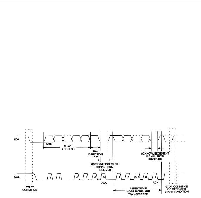
The following bus protocol has been defined (See Figure 4):
∙Data transfer may be initiated only when the bus is not busy.
∙During data transfer, the data line must remain stable whenever the clock line is HIGH. Changes in the data line while the clock line is high will be interpreted as control signals.
Accordingly, the following bus conditions have been defined:
Bus not busy: Both data and clock lines remain HIGH.
Start data transfer: A change in the state of the data line, from HIGH to LOW, while the clock is HIGH, defines a START condition.
Stop data transfer: A change in the state of the data line, from LOW to HIGH, while the clock line is HIGH, defines the STOP condition.
6 of 16 |
102299 |
DS1621
Data valid: The state of the data line represents valid data when, after a START condition, the data line is stable for the duration of the HIGH period of the clock signal. The data on the line must be changed during the LOW period of the clock signal. There is one clock pulse per bit of data.
Each data transfer is initiated with a START condition and terminated with a STOP condition. The number of data bytes transferred between START and STOP conditions is not limited and is determined by the master device. The information is transferred byte–wise and each receiver acknowledges with a ninth–bit.
Within the bus specifications a regular mode (100 kHz clock rate) and a fast mode (400 kHz clock rate) are defined. The DS1621 works in both modes.
Acknowledge: Each receiving device, when addressed, is obliged to generate an acknowledge after the reception of each byte. The master device must generate an extra clock pulse which is associated with this acknowledge bit.
A device that acknowledges must pull down the SDA line during the acknowledge clock pulse in such a way that the SDA line is stable LOW during the HIGH period of the acknowledge related clock pulse. Of course, setup and hold times must be taken into account. A master must signal an end of data to the slave by not generating an acknowledge bit on the last byte that has been clocked out of the slave. In this case, the slave must leave the data line HIGH to enable the master to generate the STOP condition.
DATA TRANSFER ON 2–WIRE SERIAL BUS Figure 4
Figure 4 details how data transfer is accomplished on the 2–wire bus. Depending upon the state of the R/W bit, two types of data transfer are possible:
1.Data transfer from a master transmitter to a slave receiver. The first byte transmitted by the master is the slave address. Next follows a number of data bytes. The slave returns an acknowledge bit after each received byte.
2.Data transfer from a slave transmitter to a master receiver. The first byte, the slave address, is transmitted by the master. The slave then returns an acknowledge bit. Next follows a number of data bytes transmitted by the slave to the master. The master returns an acknowledge bit after all received bytes other than the last byte. At the end of the last received byte, a ‘not acknowledge’ is returned.
7 of 16 |
102299 |

DS1621
The master device generates all of the serial clock pulses and the START and STOP conditions. A transfer is ended with a STOP condition or with a repeated START condition. Since a repeated START condition is also the beginning of the next serial transfer, the bus will not be released.
The DS1621 may operate in the following two modes:
1.Slave receiver mode: Serial data and clock are received through SDA and SCL. After each byte is received an acknowledge bit is transmitted. START and STOP conditions are recognized as the beginning and end of a serial transfer. Address recognition is performed by hardware after reception of the slave address and direction bit.
2.Slave transmitter mode: The first byte is received and handled as in the slave receiver mode. However, in this mode the direction bit will indicate that the transfer direction is reversed. Serial data is transmitted on SDA by the DS1621 while the serial clock is input on SCL. START and STOP conditions are recognized as the beginning and end of a serial transfer.
SLAVE ADDRESS
A control byte is the first byte received following the START condition from the master device. The control byte consists of a 4-bit control code; for the DS1621, this is set as 1001 binary for read and write operations. The next 3 bits of the control byte are the device select bits (A2, A1, A0). They are used by the master device to select which of eight devices are to be accessed. These bits are in effect the 3 least
significant bits of the slave address. The last bit of the control byte (R/ W ) defines the operation to be performed. When set to a “1” a read operation is selected, when set to a “0” a write operation is selected. Following the START condition the DS1621 monitors the SDA bus checking the device type identifier being transmitted. Upon receiving the 1001 code and appropriate device select bits, the slave device outputs an acknowledge signal on the SDA line.
8 of 16 |
102299 |
DS1621
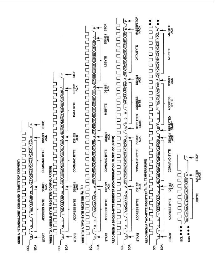
2-WIRE SERIAL COMMUNICATION WITH DS1621 Figure 5
9 of 16 |
102299 |

DS1621
COMMAND SET
Data and control information is read from and written to the DS1621 in the format shown in Figure 5. To
write to the DS1621, the master will issue the slave address of the DS1621 and the R/ W bit will be set to “0”. After receiving an acknowledge, the bus master provides a command protocol. After receiving this protocol, the DS1621 will issue an acknowledge and then the master may send data to the DS1621. If the DS1621 is to be read, the master must send the command protocol as before and then issue a repeated
START condition and the control byte again, this time with the R/ W bit set to “1” to allow reading of the data from the DS1621. The command set for the DS1621 as shown in Table 3 is as follows:
Read Temperature [AAh]
This command reads the last temperature conversion result. The DS1621 will send 2 bytes, in the format described earlier, which are the contents of this register.
Access TH [A1h]
If R/ W is “0” this command writes to the TH (HIGH TEMPERATURE) register. After issuing this command, the next 2 bytes written to the DS1621, in the same format as described for reading
temperature, will set the high temperature threshold for operation of the TOUT output. If R/ W is “1” the value stored in this register is read back.
Access TL [A2h]
If R/ W is “0” this command writes to the TL (LOW TEMPERATURE) register. After issuing this command, the next 2 bytes written to the DS1621, in the same format as described for reading
temperature, will set the high temperature threshold for operation of the TOUT output. If R/ W is “1” the value stored in this register is read back.
Access Config [ACh]
If R/ W is “0” this command writes to the configuration register. After issuing this command, the next
data byte is the value to be written into the configuration register. If R/ W is “1” the next data byte read is the value stored in the configuration register.
Read Counter [A8h]
This command reads the value of the counter byte. This command is valid only if R/ W is “1”.
Read Slope [A9h]
This command reads the value of the slope counter byte from the DS1621. This command is valid only if
R/ W is “1”.
Start Convert T [EEh]
This command begins a temperature conversion. No further data is required. In one–shot mode the temperature conversion will be performed and then the DS1621 will remain idle. In continuous mode this command will initiate continuous conversions.
Stop Convert T [22h]
This command stops temperature conversion. No further data is required. This command may be used to halt a DS1621 in continuous conversion mode. After issuing this command, the current temperature
10 of 16 |
102299 |