Материал: DS1621

DS1621
Digital Thermometer and Thermostat
www.dalsemi.com
FEATURES
§Temperature measurements require no external components
§Measures temperatures from –55°C to +125°C in 0.5°C increments. Fahrenheit equivalent is –67°F to 257°F in 0.9°F increments
§Temperature is read as a 9–bit value (2- byte transfer)
§Wide power supply range (2.7V to 5.5V)
§Converts temperature to digital word in 1 second
§Thermostatic settings are user definable and nonvolatile
§Data is read from/written via a two–wire serial interface (open drain I/O lines)
§Applications include thermostatic controls, industrial systems, consumer products, thermometers, or any thermal sensitive system
§8–pin DIP or SOIC package (150-MIL and
208-MIL)
PIN ASSIGNMENT
SDA |
|
|
|
|
1 |
8 |
|
|
|
VDD |
|
|
|
|
|
|
|
||||
|
|
|
|
|
|
|
|
|
||
SCL |
|
|
2 |
7 |
|
|
|
A0 |
||
|
|
|
|
|
|
|||||
|
|
|
|
|
|
|
|
|
||
TOUT |
|
|
3 |
6 |
|
|
|
A1 |
||
|
|
|
|
|
|
|||||
GND |
|
|
4 |
5 |
|
|
|
A2 |
||
|
|
|
|
|
|
|||||
|
|
|
|
|
|
|
|
|
||
|
|
|
|
|
|
|
|
|
|
|
DS1621S 8-PIN SOIC (150-MIL)
DS1621V 8-PIN SOIC (208-MIL)
See Mech Drawings Section
SDA |
|
|
|
|
|
VDD |
|
1 |
8 |
|
|||
|
|
|||||
|
|
|
|
|
||
SCL |
|
2 |
7 |
|
A0 |
|
|
|
|||||
|
|
|
|
|
||
TOUT |
|
3 |
6 |
|
A1 |
|
|
|
|||||
GND |
|
4 |
5 |
|
A2 |
|
|
|
|||||
|
|
|
|
|
||
|
|
|
|
|
|
|
|
DS1621 8-PIN DIP (300-MIL) |
|
See Mech Drawings Section |
PIN DESCRIPTION |
|
SDA |
- 2-Wire Serial Data Input/Output |
SCL |
- 2-Wire Serial Clock |
GND |
- Ground |
TOUT |
- Thermostat Output Signal |
A0 |
- Chip Address Input |
A1 |
- Chip Address Input |
A2 |
- Chip Address Input |
VDD |
- Power Supply Voltage |
DESCRIPTION
The DS1621 Digital Thermometer and Thermostat provides 9–bit temperature readings which indicate the temperature of the device. The thermal alarm output, TOUT, is active when the temperature of the device exceeds a user–defined temperature TH. The output remains active until the temperature drops below user defined temperature TL, allowing for any hysteresis necessary.
User-defined temperature settings are stored in nonvolatile memory so parts may be programmed prior to insertion in a system. Temperature settings and temperature readings are all communicated to/from the DS1621 over a simple two–wire serial interface.
1 of 16 |
102299 |
|
|
|
DS1621 |
|
|
DETAILED PIN DESCRIPTION Table 1 |
|
||
|
PIN |
SYMBOL |
DESCRIPTION |
|
|
1 |
SDA |
Data input/output pin for 2-wire serial communication port. |
|
|
2 |
SCL |
Clock input/output pin for 2-wire serial communication port. |
|
|
3 |
TOUT |
Thermostat output. Active when temperature exceeds TH; will reset when |
|
|
|
|
temperature falls below TL. |
|
|
4 |
GND |
Ground pin. |
|
|
5 |
A2 |
Address input pin. |
|
|
6 |
A1 |
Address input pin. |
|
|
7 |
A0 |
Address input pin. |
|
|
8 |
VDD |
Supply voltage input power pin. (2.7V – 5.5V) |
|
OPERATION
Measuring Temperature
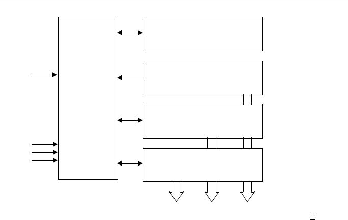
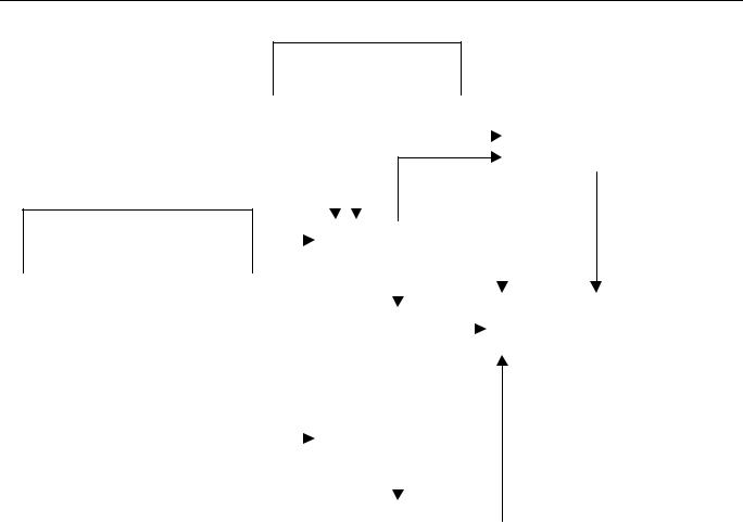
A block diagram of the DS1621 is shown in Figure 1. The DS1621 measures temperatures through the use of an onboard proprietary temperature measurement technique. A block diagram of the temperature measurement circuitry is shown in Figure 2.
The DS1621 measures temperature by counting the number of clock cycles that an oscillator with a low temperature coefficient goes through during a gate period determined by a high temperature coefficient oscillator. The counter is preset with a base count that corresponds to –55°C. If the counter reaches 0 before the gate period is over the temperature register, which is also preset to the –55°C value, is incremented indicating that the temperature is higher than –55°C.
At the same time, the counter is preset with a value determined by the slope accumulator circuitry. This circuitry is needed to compensate for the parabolic behavior of the oscillators over temperature. The counter is then clocked again until it reaches 0. If the gate period is still not finished, then this process repeats.
The slope accumulator is used to compensate for the nonlinear behavior of the oscillators over temperature, yielding a high resolution temperature measurement. This is done by changing the number of counts necessary for the counter to go through for each incremental degree in temperature. To obtain the desired resolution, both the value of the counter and the number of counts per °C (the value of the slope accumulator) at a given temperature must be known.
This calculation is done inside the DS1621 to provide 0.5°C resolution. The temperature reading is provided in a 9–bit, two’s complement reading by issuing the READ TEMPERATURE command. Table 2 describes the exact relationship of output data to measured temperature. The data is transmitted through the 2–wire serial interface, MSB first. The DS1621 can measure temperature over the range of –55°C to +125°C in 0.5°C increments. For Fahrenheit usage a lookup table or conversion factor must be used.
2 of 16 |
102299 |
DS1621
DS1621 FUNCTIONAL BLOCK DIAGRAM Figure 1
STATUS REGISTER &
CONTROL LOGIC
SCL
TEMPERATURE SENSOR
ADDRESS
AND
SDA 
 I/O CONTROL
HIGH TEMP TRIGGER, TH
A0
A1
A2
LOW TEMP TRIGGER, TL
DIGITAL COMPARATOR/LOGIC |
|
TOUT |
|
||
|
|
|
3 of 16 |
102299 |
DS1621
TEMPERATURE MEASURING CIRCUITRY Figure 2
SLOPE ACCUMULATOR
|
|
|
|
|
|
|
|
|
PRESET |
|
|
|
|
|
|
|
COMPARE |
|
|
|
|
|
|
|
||
|
|
|
|
|
|
|
||
|
|
|
|
|
|
|
|
|
|
|
|
|
|
|
|
|
|
LOW TEMPERATURE |
|
|
|
|
|
|
COUNTER |
|
|
|
PRESET |
SET/CLEAR |
|||
COEFFICIENT OSCILLATOR |
|
|
|
|
|
|
|
|
|
LSB |
|||||
|
|
|
|
|
|
|
|
|
|
|
|
|
|
||
|
|
|
|
|
|
|
|
|
|
|
|
|
|
||
|
|
|
|
|
|
|
|
|
|
INC |
|
|
|
||
|
|
|
|
|
|
|
|
|
|
|
TEMPERATURE REGISTER |
||||
|
|
|
|
|
|
|
|
=0 |
|||||||
|
|
|
|
|
|
|
|
|
|
|
|
||||
|
|
|
|
|
|
|
|
|
|
|
|||||
|
|
|
|
|
|
|
|
|
|
|
|
|
|
|
|
|
|
|
|
|
|
|
|
|
|
|
|
|
|
|
|
|
|
|
|
|
|
|
|
|
|
|
|
|
|
|
|
|
|
|
|
|
|
|
|
|
|
|
|
|
|
|
|
HIGH TEMPERATURE |
|
|
|
|
|
|
|
|
COUNTER |
|
|||
COEFFICIENT OSCILLATOR |
|
|
|
|||
|
|
|
|
|
|
|
|
|
|
|
|
|
STOP |
|
|
|
|
|
|
|
|
|
|
|
|
|
|
|
|
|
|
=0 |
||
|
|
|
||||
|
|
|
|
|
||
|
|
|
|
|
|
|
TEMPERATURE/DATA RELATIONSHIPS Table 2
TEMPERATURE |
DIGITAL OUTPUT |
DIGITAL OUTPUT |
|
(Binary) |
(Hex) |
+125°C |
01111101 00000000 |
7B00h |
+25°C |
00011001 00000000 |
1900h |
+½°C |
00000001 00000000 |
0080h |
+0°C |
00000000 00000000 |
0000h |
-½°C |
11111111 10000000 |
FF80h |
-25°C |
11100111 00000000 |
E700h |
-55°C |
11001001 00000000 |
C900h |
Since data is transmitted over the 2–wire bus MSB first, temperature data may be written to/read from the DS1621 as either a single byte (with temperature resolution of 1°C) or as two bytes. The second byte would contain the value of the least significant (0.5°C) bit of the temperature reading as shown in Table 1. Note that the remaining 7 bits of this byte are set to all "0"s.
Temperature is represented in the DS1621 in terms of a ½°C LSB, yielding the following 9–bit format:
MSB |
|
|
|
|
|
|
|
|
LSB |
|
|
|
|
|
|
|
|
1 |
1 |
1 |
0 |
0 |
1 |
1 |
1 |
|
0 |
0 |
0 |
0 |
0 |
0 |
0 |
0 |
|
|
|
|
|
|
|
|
|
|
|
|
|
|
|
|
|
|
|
|
|
|
|
|
|
|
|
|
T = -25°C |
|
|
|
|
|
|
|
|
|
|
|
|
|
|
|
|
4 of 16 |
|
|
|
|
|
|
102299 |
||
DS1621
Higher resolutions may be obtained by reading the temperature and truncating the 0.5°C bit (the LSB) from the read value. This value is TEMP_READ. The value left in the counter may then be read by issuing a READ COUNTER command. This value is the count remaining (COUNT_REMAIN) after the gate period has ceased. By loading the value of the slope accumulator into the count register (using the READ SLOPE command), this value may then be read, yielding the number of counts per degree C (COUNT_PER_C) at that temperature. The actual temperature may be then be calculated by the user using the following:
TEMPERATURE=TEMP_READ-0.25 + (COUNT _ PER _ C − COUNT _ REMAIN)
COUNT _ PER _ C
Thermostat Control
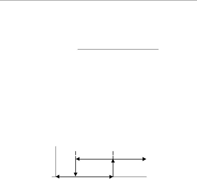
In its operating mode, the DS1621 functions as a thermostat with programmable hysteresis as shown in Figure 3. The thermostat output updates as soon as a temperature conversion is complete.
When the DS1621’s temperature meets or exceeds the value stored in the high temperature trip register (TH), the output becomes active and will stay active until the temperature falls below the temperature stored in the low temperature trigger register (TL). In this way, any amount of hysteresis may be obtained.
The active state for the output is programmable by the user so that an active state may either be a logic "1" (VDD) or a logic "0" (0V).
THERMOSTAT OUTPUT OPERATION Figure 3
DQ (Thermostat output, Active=High)
TL |
TH |
T (°C) |
OPERATION AND CONTROL
The DS1621 must have temperature settings resident in the TH and TL registers for thermostatic operation. A configuration/status register also determines the method of operation that the DS1621 will use in a particular application, as well as indicating the status of the temperature conversion operation.
The configuration register is defined as follows:
|
DONE |
THF |
TLF |
NVB |
1 |
0 |
POL |
1SHOT |
|
|
|
|
|
|
|
|
|
|
|
where |
|
|
|
|
|
|
|
|
|
DONE |
= Conversion Done bit. “1” = Conversion complete, “0” = Conversion in progress. |
||||||||
5 of 16 |
102299 |