Материал: m083700e
76• Fieldbus Controller 750-837, /02x-000, 750-838, /02x-000 Data Exchange
|
programmable fieldbus controller |
|
|
|
|
memory area |
|
|
|
|
for input data |
|
|
|
|
word 0 |
1 |
|
|
fieldbus |
input |
|
I/O modules |
|
|
|
|
||
|
modules |
|
|
|
|
word 255 |
|
|
|
|
word 256 |
3 |
|
|
|
|
|
|
|
|
PFC |
IEC 61131 |
|
|
|
program |
|
|
|
|
input |
|
|
|
|
|
|
|
|
|
variables |
|
|
|
|
word 511 |
CPU |
|
|
|
memory area |
|
|
|
|
for output data |
|
|
|
|
word 0 |
2 |
|
|
|
output |
|
|
|
|
modules |
|
|
|
|
word 255 |
4 |
I |
O |
|
word 256 |
|||
|
|
|
|
|
|
PFC |
|
|
|
|
output |
|
|
|
|
variables |
|
|
|
|
word 511 |
|
|
|
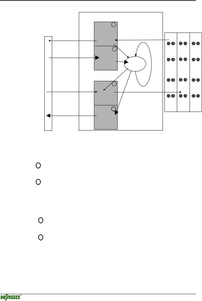
Fig. 3-11: Memory areas and data exchange for a fieldbus controller |
|
g012434e |
||
In its memory space word 0 ... 255, the controller process image contains the physical data of the bus modules.
1The data of the input modules can be read by the CPU and from the fieldbus side.
2In the same manner, writing to the output modules is possible from the CPU and from the fieldbus side. The value of the master is written to the output while writing on an output.
The PFC variables are filled in the memory space word 256 ... 511 of the process image.
3The PFC input variables are written in the input memory space from the fieldbus side and read by the CPU for further processing.
4The variables processed by the CPU via the IEC 61131-3 program are filled in the output memory space and can be read out by the master.
WAGO-I/O-SYSTEM 750
CANopen
Fieldbus Controller 750-837, /02x-000, 750-838, /02x-000 |
• 77 |
Data Exchange |
|
|
|
In addition, the controller offers further memory spaces which, however, cannot be accessed from the fieldbus side:
RAM The RAM memory is used to create variables not required for communication with the interfaces but for internal processing, such as computation of results.
Retain The retain memory is a non-volatile memory, i.e. all values are retained following a voltage failure. The memory management is automatic. In this memory area, flags for the IEC 61131-3 program are filed together with variables without memory space addressing or variables which are explicitly defined with "var retain".
Note
The automatic memory management can cause a data overlap. For this reason, we recommend not to use a mix of flags and retain variables.
Code- The IEC 61131-3 program is filed in the code memory. The code Memory memory is a flash ROM. Once the supply voltage is applied, the program is transmitted from the flash to the RAM memory. After
an error-free start-up, the PFC cycle starts when the operating mode switch is turned to its upper position or by a start command from WAGO-I/O-PRO CAA.
WAGO-I/O-SYSTEM 750
CANopen
78• Fieldbus Controller 750-837, /02x-000, 750-838, /02x-000 Data Exchange
3.1.5.4 Addressing
3.1.5.4.1 Fieldbus specific Addressing
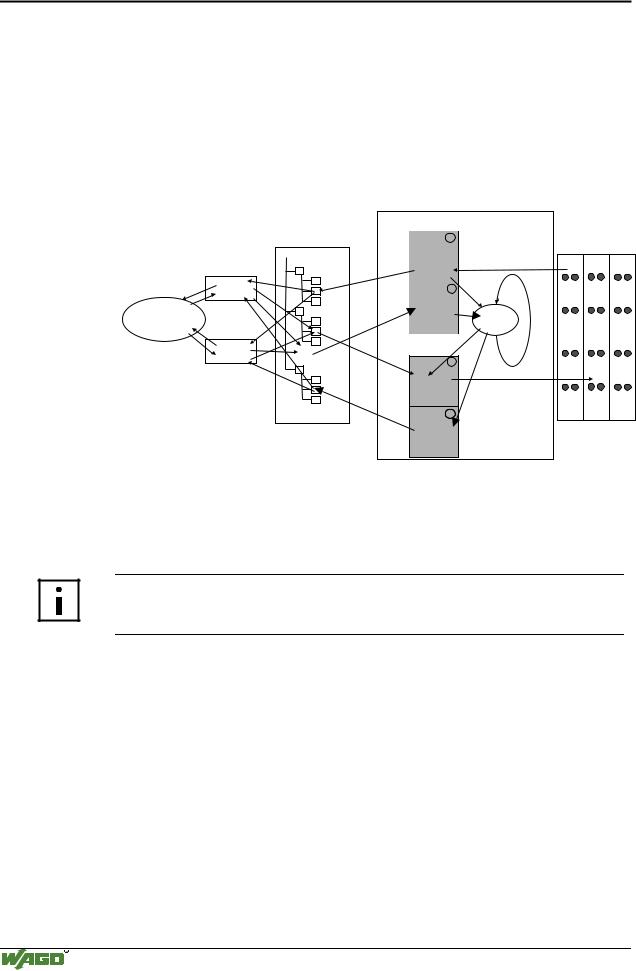
Upon switching on the supply voltage, the data of the process image is mapped into an object directory (initialization). A CANopen Fieldbus Master uses the 16 bit indexes and 8 bit sub-indexes of the object directory in order to address and to access the data via PDOs or SDOs.
Therefore, the position of the data in the process image is of no direct significance for the CANopen user.
|
|
Programmable fieldbus controller |
|
|
||
|
|
memory area |
|
|
|
|
|
|
for input data |
|
|
|
|
|
Object directory() |
word 0 |
1 |
|
|
|
|
|
|
|
|
||
|
|
input |
|
|
I/O modules |
|
|
Index |
modules |
|
|
|
|
|
Sub- |
|
|
|
|
|
|
Index |
word 255 |
|
|
|
|
|
|
|
|
|
|
|
PDO |
|
word 256 |
3 |
IEC 61131 |
|
|
|
|
PFC |
|
|
|
|
|
|
|
program |
|
|
|
|
|
input |
|
|
|
|
fieldbus |
|
|
|
|
|
|
|
variables |
|
CPU |
|
|
|
master |
|
word 511 |
|
|
|
|
|
|
|
|
|
||
|
. |
memory area |
|
|
|
|
SDO |
for output data |
|
|
|
||
. |
|
|
|
|||
|
. |
word 0 |
|
|
|
|
|
|
2 |
|
|
|
|
|
|
output |
|
|
|
|
|
|
modules |
|
|
|
|
|
|
word 255 |
|
|
|
|
|
|
word 256 |
4 |
|
I |
O |
|
|
PFC |
|
|
|
|
|
|
output |
|
|
|
|
|
|
variables |
|
|
|
|
|
|
word 511 |
|
|
|
|
Fig. 3-12: Fieldbus specific data exchange for a CANopen fieldbus controller |
g012432e |
3.1.5.4.1.1Indexing the bus module data
If a customer specific configuration was stored prior to initializing, and if the currently connected module configuration coincides with the one stored last, the initialization is made with this configuration.
More Information
Chapter 3.1.7.6 "Application specific mapping" has an example of how to initialize a customer specific configuration.
In every other case, the object directory is assigned with a default configuration according to the device profile DS 401 when initializing.
Here, the entry into the object directory is made separately according to data width (1 bit, 1 byte, 2 byte, 3 byte, etc.) and input and output.
Any physical arrangement of the bus modules in a node is possible.
Data width = 1 Word / channel |
Data width = 1 Bit / channel |
|
|
Analog input modules |
Digital input modules |
Analog output modules |
Digital output modules |
Input modules for thermal elements |
Digital output modules with diagnosis (2 Bit / channel) |
Input modules for resistance sensors |
Power supply modules with fuse holder / diagnosis |
Pulse width output modules |
Solid State power relay |
Interface module |
Relay output modules |
Up/down counter |
|
I/O modules for angle and path measurement |
|
|
|
Table 3-1: I/O module data width
WAGO-I/O-SYSTEM 750
CANopen
Fieldbus Controller 750-837, /02x-000, 750-838, /02x-000 |
• 79 |
Data Exchange |
|
|
|
Note
For the number of input and output bits or bytes of the individually activated on I/O modules please refer to the corresponding I/O module description.
The digital module data is taken into consideration first.
CANopen does not transmit the data bit by bit. The digital module data is grouped into bytes and assigned to the corresponding index, digital input data to index 0x2000 (0x6000), digital output data to index 0x2100 (0x6200).
The assignment of bus module data having a width of 1 byte or more, are analog modules and assigned to the individual indexes.
The table shows a review of the indexes of the bus module data.
Data width |
input modules |
|
output modules |
|
|
|
|
||
|
Index |
|||
|
|
|
||
|
|
|
|
|
1 |
Bit digital |
0x2000 (0x6000) |
|
0x2100 (0x6200) |
|
|
|
|
|
1 |
Byte specialty modules |
0x2200 |
|
0x2300 |
|
|
|
|
|
2 |
Byte specialty modules |
0x2400 (0x6401) |
|
0x2500 (0x6411) |
|
|
|
|
|
3 |
Byte specialty modules |
0x2600 |
|
0x2700 |
|
|
|
|
|
4 |
Byte specialty modules |
0x2800 |
|
0x2900 |
|
|
|
|
|
5 |
Byte specialty modules |
0x3000 |
|
0x3100 |
|
|
|
|
|
6 |
Byte specialty modules |
0x3200 |
|
0x3300 |
|
|
|
|
|
7 |
Byte specialty modules |
0x3400 |
|
0x3500 |
|
|
|
|
|
8 |
Byte specialty modules |
0x3600 |
|
0x3700 |
|
|
|
|
|
Table 3-2: Indexing of bus module data in the object directory
Every index has a maximum of 256 sub-indexes (Sub-Index 0-255).
The number of data inputs is indicated in sub-index 0, whereby the data is filled in blocks in the following sub-indexes.
The block size depends on the data width of the specific bus module.
WAGO-I/O-SYSTEM 750
CANopen
80• Fieldbus Controller 750-837, /02x-000, 750-838, /02x-000 Data Exchange
Sub-Index |
Contents |
|
|
0 |
Number of Data blocks |
1 |
First Data block with the data width of the I/O module |
2 |
Second Data block with the data width of the I/O module |
... |
... |
Table 3-3: Sub-indexing of the bus module data in the object directory
Note
Please refer to chapter 5.3.4.1 "Initialization" for a detailed description of how to set the default configuration.
Attention
A process image restructuring may result if a node is changed or extended. In this case the process data addresses also change in comparison with earlier ones. In the event of adding modules, take the process data of all previous modules into account.
Example:
The bus module configuration includes:
1)5 digital 2 channel input modules (i.e. 750-400),
2)one digital 4 channel output module (i.e. 750-504) and
3)two 2 channel analog output modules with 2 bytes per channel (i.e. 750-552).
to 1) Indexing the data of the 5 digital 2 channel input modules:
Index: |
Sub- |
Contents: |
|
|
|
|
|
Description: |
|
|
Index: |
|
|
|
|
|
|
|
|
|
|
|
|
|
|
|
|
|
|
0x2000 |
0 |
2 |
|
|
|
|
|
|
number of dig. 8 Bit input blocks |
1 |
D4.2 D4.1 D3.2 D3.1 D2.2 D2.1 D1.2 |
D1.1 *) |
1. dig. input block |
||||||
|
2 |
0 |
0 |
0 |
0 |
0 |
0 D5.2 |
D5.1 *) |
2. dig. input block |
*) D1.1 = Data bit module 1 channel 1, D1.2 = Data bit module 1channel 2, etc.
to 2) Indexing the data of the digital 4 channel output module:
Index: |
Sub- |
Contents: |
|
|
Description: |
|
|
Index: |
|
|
|
|
|
|
|
|
|
|
|
|
0x2100 |
0 |
1 |
|
|
|
number of dig. 8 Bit input blocks |
1 |
0 |
0 |
0 |
0 D1.4 D1.3 D1.2 D1.1 *) |
dig. output block |
|
*) D1.1 = Data bit module 1 channel 1, D1.2 = Data bit module 1 channel 2, etc.
to 3) Indexing the data of the 2 analog 2 channel output modules:
Index: |
Sub- |
Contents: |
Description: |
|
Index: |
|
|
|
|
|
|
|
0 |
4 |
number of 2 Byte specialty channels |
0x2900 |
1 |
D1.1 *) |
1. output channel |
2 |
D1.2 *) |
2. output channel |
|
|
3 |
D2.1 *) |
3. output channel |
|
4 |
D2.2 *) |
4. output channel |
*) D1.1 = Data word module 1 channel 1, D1.2 = Data word module 1 channel 2, etc.
3.1.5.4.1.2Indexing the PFC Variables
The entry of the PFC variables into the object directory is made separate according to data type (Integer8, Unsigned8, Boolean, Integer16, etc...) and input and output.
WAGO-I/O-SYSTEM 750
CANopen