Материал: MJW16212
MOTOROLA
SEMICONDUCTOR TECHNICAL DATA
Order this document by MJW16212/D
SCANSWITCH
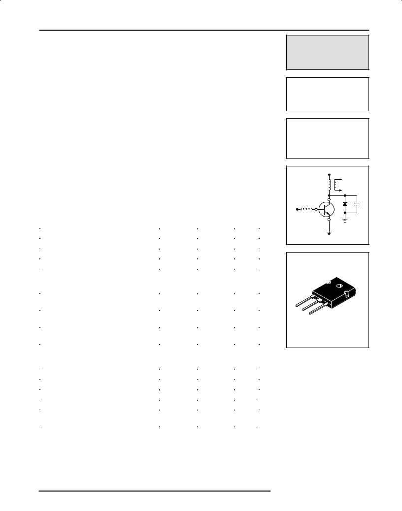
NPN Bipolar Power Deflection Transistor
For High and Very High Resolution Monitors
The MJW16212 is a state±of±the±art SWITCHMODE bipolar power transistor. It is specifically designed for use in horizontal deflection circuits for 20 mm diameter neck, high and very high resolution, full page, monochrome monitors.
•1500 Volt Collector±Emitter Breakdown Capability
•Typical Dynamic Desaturation Specified (New Turn±Off Characteristic)
•Application Specific State±of±the±Art Die Design
•Fast Switching:
200 ns Inductive Fall Time (Typ)
2000 ns Inductive Storage Time (Typ)
•Low Saturation Voltage:
0.15Volts at 5.5 Amps Collector Current and 2.5 A Base Drive
•Low Collector±Emitter Leakage Current Ð 250 μA Max at 1500 Volts Ð V CES
•High Emitter±Base Breakdown Capability For High Voltage Off Drive Circuits Ð
8.0Volts (Min)
MAXIMUM RATINGS
Rating |
|
Symbol |
Value |
Unit |
|
|
|
|
|
Collector±Emitter Breakdown Voltage |
VCES |
1500 |
Vdc |
|
Collector±Emitter Sustaining Voltage |
VCEO(sus) |
650 |
Vdc |
|
Emitter±Base Voltage |
|
VEBO |
8.0 |
Vdc |
RMS Isolation Voltage (2) |
|
VISOL |
|
V |
(for 1 sec, TA = 25_C, |
Per Fig. 14 |
|
Ð |
|
Rel. Humidity < 30%) |
Per Fig. 15 |
|
Ð |
|
|
|
|
|
|
Collector Current Ð Continuous |
|
IC |
10 |
Adc |
Collector Current Ð Pulsed (1) |
|
ICM |
15 |
|
Base Current Ð Continuous |
|
IB |
5.0 |
Adc |
Base Current Ð Pulsed (1) |
|
IBM |
10 |
|
Maximum Repetitive Emitter±Base |
W (BER) |
0.2 |
mJ |
|
Avalanche Energy |
|
|
|
|
|
|
|
|
|
Total Power Dissipation @ TC = 25_C |
PD |
150 |
Watts |
|
Total Power Dissipation @ TC = 100_C |
|
39 |
|
|
Derated above TC = 25_C |
|
|
1.49 |
W/_C |
Operating and Storage Temperature Range |
TJ, Tstg |
± 55 to 125 |
_C |
|
THERMAL CHARACTERISTICS |
|
|
|
|
|
|
|
|
|
Characteristic |
|
Symbol |
Max |
Unit |
|
|
|
|
|
Thermal Resistance Ð Junction to Case |
RqJC |
0.67 |
_C/W |
|
Lead Temperature for Soldering Purposes |
TL |
275 |
_C |
|
1/8″ from the case for 5 seconds |
|
|
|
|
|
|
|
|
|
(1)Pulse Test: Pulse Width = 5.0 ms, Duty Cycle v 10%.
(2)Proper strike and creepage distance must be provided.
Preferred devices are Motorola recommended choices for future use and best overall value.
SCANSWITCH and SWITCHMODE are trademarks of Motorola Inc.
MJF18002 (See MJE18002)
MJF18004 (See MJE18004)
MJF18006 (See MJE18006)
MJF18008 (See MJE18008)
MJW16212*
*Motorola Preferred Device
POWER TRANSISTOR
10 AMPERES
1500 VOLTS ± VCES
50 AND 150 WATTS
CASE 340F±03
TO±247AE
REV 1
Motorola, Inc. 1995
MJW16212
ELECTRICAL CHARACTERISTICS (TC = 25_C unless otherwise noted)
Characteristic |
Symbol |
Min |
Typ |
Max |
Unit |
|
|
|
|
|
|
OFF CHARACTERISTICS (2) |
|
|
|
|
|
|
|
|
|
|
|
Collector Cutoff Current (VCE = 1500 V, VBE = 0 V) |
ICES |
Ð |
Ð |
250 |
mAdc |
Collector Cutoff Current (VCE = 1200 V, VBE = 0 V) |
|
Ð |
Ð |
25 |
|
Emitter±Base Leakage (VEB = 8.0 Vdc, IC = 0) |
IEBO |
Ð |
Ð |
25 |
mAdc |
Emitter±Base Breakdown Voltage (IE = 1.0 mA, IC = 0) |
V(BR)EBO |
8.0 |
11 |
Ð |
Vdc |
Collector±Emitter Sustaining Voltage (Table 1) (IC = 10 mAdc, IB = 0) |
VCEO(sus) |
650 |
Ð |
Ð |
Vdc |
ON CHARACTERISTICS (2) |
|
|
|
|
|
|
|
|
|
|
|
Collector±Emitter Saturation Voltage (IC = 5.5 Adc, IB = 2.2 Adc) |
VCE(sat) |
Ð |
0.15 |
1.0 |
Vdc |
Collector±Emitter Saturation Voltage (IC = 3.0 Adc, IB = 400 mAdc) |
|
Ð |
0.14 |
1.0 |
|
Base±Emitter Saturation Voltage (IC = 5.5 Adc, IB = 2.2 Adc) |
VBE(sat) |
Ð |
0.9 |
1.5 |
Vdc |
DC Current Gain (IC = 1.0 A, VCE = 5.0 Vdc) |
hFE |
Ð |
24 |
Ð |
Ð |
DC Current Gain (IC = 10 A, VCE = 5.0 Vdc) |
|
4.0 |
6.0 |
10 |
|
DYNAMIC CHARACTERISTICS |
|
|
|
|
|
|
|
|
|
|
|
Dynamic Desaturation Interval (IC = 5.5 A, IB1 = 2.2 A, LB = 1.5 mH) |
tds |
Ð |
350 |
Ð |
ns |
Output Capacitance |
Cob |
Ð |
180 |
350 |
pF |
(VCE = 10 Vdc, IE = 0, ftest = 100 kHz) |
|
|
|
|
|
Gain Bandwidth Product |
fT |
Ð |
2.75 |
Ð |
MHz |
(VCE = 10 Vdc, IC = 0.5 A, ftest = 1.0 MHz) |
|
|
|
|
|
Emitter±Base Turn±Off Energy |
EB(off) |
Ð |
35 |
Ð |
mJ |
(EB(avalanche) = 500 ns, RBE = 22 W) |
|
|
|
|
|
Collector±Heatsink Capacitance Ð MJF16212 Isolated Package |
Cc±hs |
Ð |
5.0 |
Ð |
pF |
(Mounted on a 1″ x 2″ x 1/16″ Copper Heatsink, VCE = 0, ftest = 100 kHz) |
|
|
|
|
|
SWITCHING CHARACTERISTICS |
|
|
|
|
|
|
|
|
|
|
|
Inductive Load (IC = 5.5 A, IB = 2.2 A), High Resolution Deflection |
|
|
|
|
ns |
Simulator Circuit Table 2 |
|
|
|
|
|
Storage |
tsv |
Ð |
2000 |
4000 |
|
Fall Time |
|
||||
tfi |
Ð |
200 |
350 |
|
|
|
|
(2) Pulse Test: Pulse Width = 300 ms, Duty Cycle v 2.0%.
SAFE OPERATING AREA
(A) |
100 |
|
|
|
|
|
|
|
|
|
|
50 |
|
|
|
|
|
|
|
|
|
|
|
CURRENT |
20 |
|
|
|
|
|
|
|
|
10 ms |
|
10 |
|
|
|
|
|
|
|
|
|||
|
|
|
|
|
|
|
|
|
|
||
5 |
|
|
|
|
|
|
|
|
|
|
|
COLLECTOR±EMITTER |
|
|
|
|
|
|
|
|
|
100 |
|
2 |
|
|
|
|
|
|
|
|
|
||
|
|
|
|
MJH16212 |
|
|
5 ms |
ns |
|||
1 |
|
|
|
|
|
|
|
|
|
II |
|
0.5 |
|
|
|
|
|
|
|
DC |
|
||
|
|
|
|
|
|
|
|
|
|||
|
|
|
|
|
|
|
|
|
|
||
0.2 |
|
|
BONDING WIRE LIMIT |
|
|
|
|
||||
0.1 |
|
|
|
|
|
|
|||||
|
|
THERMAL LIMIT |
|
|
|
|
|||||
0.05 |
|
|
SECOND BREAKDOWN |
|
|
|
|||||
, |
|
TJ = 25°C |
|
|
|
|
|
|
|
||
C |
|
|
|
|
|
|
|
|
|||
I |
0.02 |
|
|
|
|
|
|
|
|||
|
0.01 |
2 |
3 |
5 |
7 |
10 |
20 30 |
50 |
70100 |
200 300 |
500700 1K |
|
1 |
||||||||||
|
|
|
|
VCE, COLLECTOR±EMITTER VOLTAGE (V) |
|
||||||
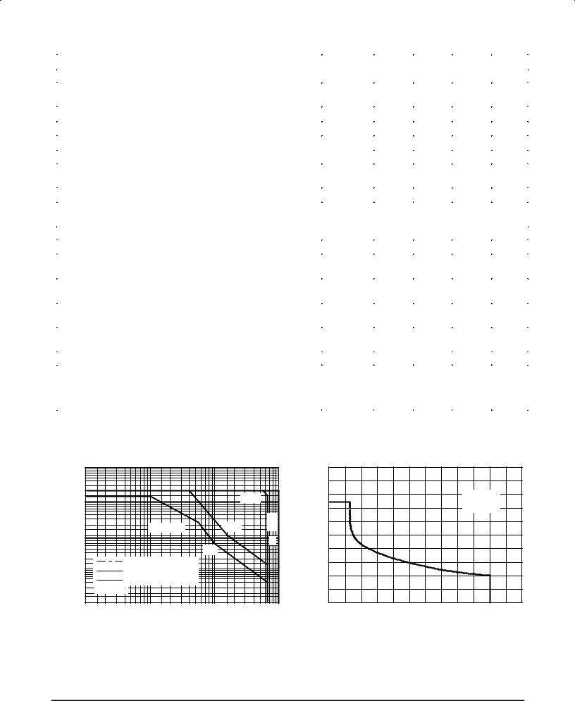
Figure 1. Maximum Forward Bias
Safe Operating Area
|
18 |
|
|
|
|
|
(A) |
|
|
|
|
|
IC/IB = 5 |
CURRENT |
|
|
|
|
|
|
14 |
|
|
|
|
TJ ≤ 100°C |
|
|
|
|
|
|
|
|
, COLLECTOR |
10 |
|
|
|
|
|
6 |
|
|
|
|
|
|
|
|
|
|
|
|
|
C |
|
|
|
|
|
|
I |
|
|
|
|
|
|
|
2 |
|
|
|
|
|
|
0 |
300 |
600 |
900 |
1200 |
1500 |
VCE, COLLECTOR±EMITTER VOLTAGE (V)
Figure 2. Maximum Reverse Bias
Safe Operating Area
3±2 |
Motorola Bipolar Power Transistor Device Data |
MJW16212
SAFE OPERATING AREA (continued)
FORWARD BIAS
There are two limitations on the power handling ability of a transistor: average junction temperature and second breakdown. Safe operating area curves indicate IC ± VCE limits of the transistor that must be observed for reliable operation; i.e., the transistor must not be subjected to greater dissipation than the curves indicate.
The data of Figure 1 is based on TC = 25_C; TJ(pk) is variable depending on power level. Second breakdown pulse
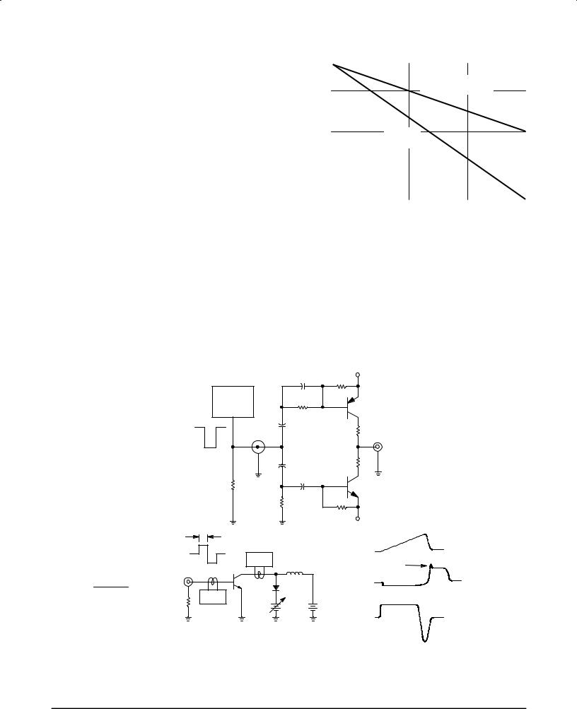
limits are valid for duty cycles to 10% but must be derated when TC ≥ 25_C. Second breakdown limitations do not derate the same as thermal limitations. Allowable current at the voltages shown on Figure 1 may be found at any case temperature by using the appropriate curve on Figure 3.
At high case temperatures, thermal limitations will reduce the power that can be handled to values less than the limitations imposed by second breakdown.
REVERSE BIAS
For inductive loads, high voltage and high current must be sustained simultaneously during turn±off, in most cases, with the base±to±emitter junction reverse biased. Under these conditions the collector voltage must be held to a safe level at or below a specific value of collector current. This can be accomplished by several means such as active clamping,
|
1 |
|
|
|
|
|
|
|
|
|
|
|
|
|
|
|
|
|
|
|
|
|
|
|
|
|
|
|
|
|
|
|
|
|
|
|
|
|
|
|
|
|
|
|
|
|
|
|
|
SECOND |
BREAKDOWN |
|
|
|
|
FACTOR |
0.8 |
|
|
|
|
|
|
|
DERATING |
|
|
|
|
|
|
|
|
|
|
|
|
|
|
|
|
||
0.6 |
|
|
|
|
|
|
|
|
|
|
|
|
|
|
|
|
|
|
|
|
|
|
|
|
|
||
DERATING |
|
|
|
|
|
|
|
|
|
|
|
|
|
|
|
|
|
DERATING |
|
|
|
|
|
|
|
||
0.4 |
|
|
|
|
|
|
|
|
|
|
|
||
POWER |
0.2 |
|
|
|
|
THERMAL |
|
|
|
|
|
|
|
|
|
|
|
|
|
|
|
|
|
|
|
||
|
|
|
|
|
|
|
|
|
|
|
|
||
|
|
|
|
|
|
|
|
|
|
|
|
||
|
0 |
|
|
|
|
|
|
|
|
|
|
|
|
|
|
|
|
|
|
|
|
|
|
|
|
|
|
|
|
|
|
|
|
|
|
|
|
|
|
|
|
|
25 |
45 |
65 |
85 |
105 |
125 |
|||||||
TC, CASE TEMPERATURE (°C)
Figure 3. Power Derating
RC snubbing, load line shaping, etc.
The safe level for these devices is specified as Reverse Biased Safe Operating Area and represents the voltage± current condition allowable during reverse biased turnoff. This rating is verified under clamped conditions so that the device is never subjected to an avalanche mode. Figure 2 gives the RBSOA characteristics.
Lcoil (ICpk)
T1 [ VCC
T1 adjusted to obtain IC(pk)
V(BR)CEO
L = 10 mH
RB2 = ∞
VCC = 20 Volts
*Tektronix *P±6042 or *Equivalent
|
Table 1. RBSOA/V(BR)CEO(SUS) Test Circuit |
|||
|
|
0.02 |
μF |
+ V ≈ 11 V |
|
|
100 |
||
|
|
|
|
|
|
H.P. 214 |
|
|
|
|
OR EQUIV. |
|
|
2N6191 |
|
P.G. |
20 |
||
|
|
|||
|
|
|
||
|
|
+ |
|
|
0 |
|
10 μF |
|
RB1 |
|
|
± |
|
|
≈ ± 35 V |
|
|
|
A |
|
|
0.02 μF |
RB2 |
|
|
|
|
||
|
50 |
+ |
± |
2N5337 |
|
|
1 μF |
|
|
|
|
500 |
|
|
|
|
|
|
100 |
|
|
|
|
± V |
T1 |
+ V |
|
|
IC(pk) |
0 V |
± V |
*IC |
|
IC |
|
|
VCE(pk) |
||
|
|
L |
|
|
A |
T.U.T. |
|
VCE |
|
|
MR856 |
|
|
|
50 |
*IB |
|
IB1 |
|
Vclamp |
VCC |
|||
|
||||
|
|
|
IB |
|
|
RBSOA |
|
|
|
|
L = 200 μH |
|
IB2 |
|
|
RB2 = 0 |
|
|
|
|
VCC = 20 Volts |
|
||
|
RB1 selected for desired IB1 |
|||
Note: Adjust ±V to obtain desired VBE(off) at Point A.
Motorola Bipolar Power Transistor Device Data |
3±3 |
MJW16212
VCE, COLLECTOR±EMITTER VOLTAGE (V)
10 |
|
|
|
|
|
|
|
|
|
|
|
10 |
|
|
|
|
|
|
|
|
|
|
7 |
IC = 2 |
4 |
5.5 |
8 |
|
10 A |
|
|
|
|
7 |
|
|
|
|
|
|
|
|
|
|
|
5 |
|
|
|
|
(V) |
|
|
|
|
|
|
|
|
|
|
|||||||
3 |
|
|
|
|
|
|
|
|
|
|
5 |
|
|
|
|
|
|
|
|
|
|
|
|
|
|
|
|
|
|
|
|
|
VOLTAGE |
IC/IB = 5 |
|
|
|
|
|
|
|
|
|||
|
|
|
|
|
|
|
|
|
|
2 |
|
|
|
|
|
|
|
|
||||
1 |
|
|
|
|
|
|
|
|
|
|
|
|
|
|
|
|
|
|
||||
2 |
|
|
|
|
|
|
|
|
|
|
|
3 |
|
|
|
|
|
|
|
|
||
|
|
|
|
|
|
|
|
|
|
|
|
TJ = 100°C |
|
|
|
|
|
|
|
|
||
|
|
|
|
|
|
|
|
|
|
|
|
|
|
|
|
|
|
|
|
|
||
0.7 |
|
|
|
|
|
|
|
|
|
|
BASE±EMITTER |
|
= 25°C |
|
|
|
|
|
|
|
|
|
0.07 |
|
|
|
|
|
|
|
|
|
|
|
|
|
|
|
|
|
|
|
|||
|
|
|
|
|
|
|
|
|
|
|
IC/IB = 10 |
|
|
|
|
|
|
|
|
|
||
0.5 |
|
|
|
|
|
|
|
|
|
|
|
|
|
|
|
|
|
|
|
|
|
|
0.3 |
|
|
|
|
|
|
|
|
|
|
|
1 |
|
|
|
|
|
|
|
|
|
|
0.2 |
TJ = 25°C |
|
|
|
|
|
|
|
|
|
|
0.7 |
|
|
|
|
|
|
|
|
|
|
0.1 |
|
|
|
|
|
|
|
|
|
|
0.5 |
|
|
|
|
|
|
|
|
|
|
|
|
|
|
|
|
|
|
|
|
|
|
|
|
|
|
|
|
|
|
|
|
||
|
|
|
|
|
|
|
|
|
|
|
|
|
|
|
|
|
|
|
|
|
|
|
0.05 |
|
|
|
|
|
|
|
|
|
|
, |
0.3 |
TJ = 100°C |
|
|
|
|
|
|
|
|
|
0.03 |
|
|
|
|
|
|
|
|
|
|
BE |
|
|
= 25°C |
|
|
|
|
|
|
|
|
|
|
|
|
|
|
|
|
|
|
V |
0.2 |
|
|
|
|
|
|
|
|
|
||
0.02 |
|
|
|
|
|
|
|
|
|
|
|
|
|
|
|
|
|
|
|
|
|
|
0.01 |
.02.03 .05 |
0.1 |
0.2 0.3 0.5 |
1 |
2 |
3 |
5 7 |
10 |
|
0.1 |
0.2 |
0.3 |
0.5 |
0.7 |
1 |
2 |
3 |
5 |
7 |
10 |
||
.01 |
|
0.1 |
||||||||||||||||||||
|
|
|
|
IB, BASE CURRENT (A) |
|
|
|
|
IC, COLLECTOR CURRENT (A) |
|
|
|
||||||||||
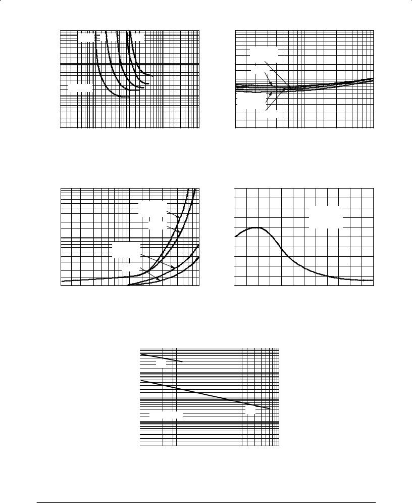
Figure 4. Typical Collector±Emitter |
Figure 5. Typical Emitter±Base |
Saturation Region |
Saturation Voltage |
(V) |
10 |
|
|
|
|
|
|
|
|
|
|
7 |
|
|
|
|
|
|
|
|
|
|
|
VOLTAGE |
5 |
|
|
|
|
|
IC/IB = 10 |
|
|
|
|
|
|
|
|
|
|
|
|
|
|||
3 |
|
|
|
|
|
TJ = 100°C |
|
|
|
||
2 |
|
|
|
|
|
|
|
|
|
|
|
COLLECTOR±EMITTER |
|
|
|
|
|
|
= 25°C |
|
|
|
|
|
|
|
|
|
|
|
|
|
|
||
1 |
|
|
|
|
|
|
|
|
|
|
|
0.7 |
|
|
|
IC/IB = 5 |
|
|
|
|
|
||
0.5 |
|
|
|
|
|
|
|
|
|||
|
|
|
TJ = 100°C |
|
|
|
|
|
|||
0.3 |
|
|
|
|
= 25°C |
|
|
|
|
|
|
0.2 |
|
|
|
|
|
|
|
|
|
||
, |
|
|
|
|
|
|
|
|
|
|
|
CE |
|
|
|
|
|
|
|
|
|
|
|
|
|
|
|
|
|
|
|
|
|
|
|
V |
0.1 |
|
|
|
|
|
|
|
|
|
|
|
|
|
|
|
|
|
|
|
|
|
|
|
0.1 |
0.2 |
0.3 |
0.5 |
0.7 |
1 |
2 |
3 |
5 |
7 |
10 |
|
5 |
|
|
|
|
|
|
FREQUENCY |
4 |
|
|
|
VCE = 10 V |
|
|
|
|
|
|
|
|
||
|
|
|
|
f(test) = 1 MHz |
|
|
|
3 |
|
|
|
TC = 25°C |
|
|
|
f τ , TRANSITION |
2 |
|
|
|
|
|
|
1 |
|
|
|
|
|
|
|
|
|
|
|
|
|
|
|
|
0 |
|
|
|
|
|
|
|
0 |
1 |
2 |
3 |
4 |
5 |
6 |
IC, COLLECTOR CURRENT (A)
Figure 6. Typical Collector±Emitter
Saturation Voltage
|
10000 |
|
|
|
|
|
|
|
|
|
|
|
|
|
|
|
|
|
|
|
|
|
|
|
|
|
|
|
|
|
|
|
|
|
|
|
|
|
|
|
|
|
|
|
|
|
5000 |
|
|
|
|
|
|
|
|
|
|
|
|
|
|
|
|
|
|
|
|
|
|
2000 |
|
|
|
Cib |
|
|
|
|
|
|
|
|
|
|
|
|
|
|
|
|
|
(pF) |
1000 |
|
|
|
|
|
|
|
|
|
|
|
|
|
|
|
|
|
|
|
|
|
500 |
|
|
|
|
|
|
|
|
|
|
|
|
|
|
|
|
|
|
|
|
|
|
CAPACITANCEC, |
|
|
test = 1 |
|
|
|
|
|
|
|
|
|
|
|
|
|
|
|
|
|
||
20 |
|
f |
MHz |
|
|
|
|
|
|
|
|
|
|
|
|
|
|
|
||||
|
200 |
|
|
|
|
|
|
|
|
|
|
|
|
|
|
|
|
|
|
|
|
|
|
100 |
|
|
|
|
|
|
|
|
|
|
|
|
|
|
|
|
|
|
|
|
|
|
50 |
|
|
|
|
|
|
|
|
|
|
|
|
|
|
|
|
|
|
|
|
|
|
10 |
|
|
|
|
|
|
|
|
|
|
|
|
|
|
|
|
|
|
|
|
|
|
5 |
|
|
|
|
|
|
|
|
|
|
|
|
|
|
|
|
|
|
|
|
|
|
2 |
|
|
|
|
|
|
|
|
|
|
|
|
|
|
|
|
|
|
|
|
|
|
1 |
|
|
|
|
|
|
|
|
|
|
|
|
|
|
|
|
|
|
|
|
|
|
1 |
2 |
3 |
5 |
7 |
10 |
20 |
30 |
50 70 100 |
|||||||||||||
VR, REVERSE VOLTAGE (V)
IC, COLLECTOR CURRENT (A)
Figure 7. Typical Transition Frequency
Cob
200300 500 1000
Figure 8. Typical Capacitance
3±4 |
Motorola Bipolar Power Transistor Device Data |
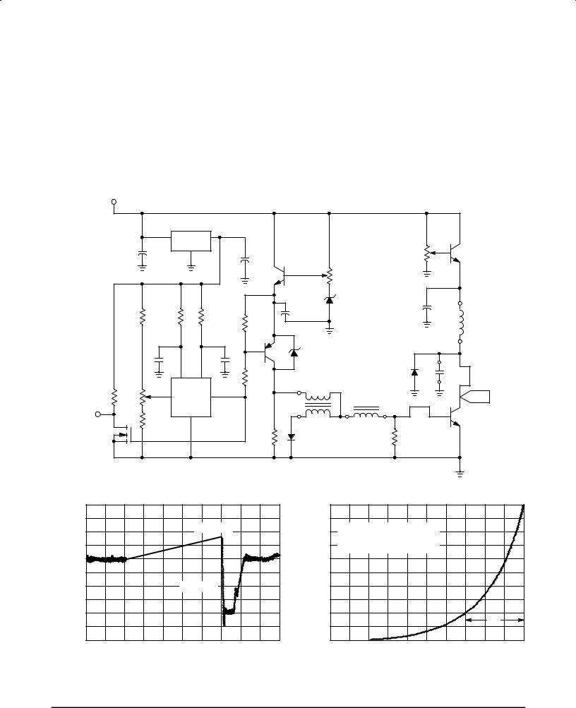
MJW16212
DYNAMIC DESATURATIION
The SCANSWITCH series of bipolar power transistors are specifically designed to meet the unique requirements of horizontal deflection circuits in computer monitor applications. Historically, deflection transistor design was focused on minimizing collector current fall time. While fall time is a valid figure of merit, a more important indicator of circuit performance as scan rates are increased is a new characteristic, ªdynamicdesaturation.º In order to assure a linear collector current ramp, the output transistor must remain in hard saturation during storage time and exhibit a rapid turn±off transition. A sluggish transition results in serious consequences. As the saturation voltage of the output transistor increases,
the voltage across the yoke drops. Roll off in the collector current ramp results in improper beam deflection and distortion of the image at the right edge of the screen. Design changes have been made in the structure of the SCANSWITCH series of devices which minimize the dynamic desaturation interval. Dynamic desaturation has been defined in terms of the time required for the VCE to rise from 1.0 to 5.0 volts (Figures 9 and 10) and typical performance at optimized drive conditions has been specified. Optimization of device structure results in a linear collector current ramp, excellent turn±off switching performance, and significantly lower overall power dissipation.
+ 24 V |
Table 2. High Resolution Deflection Application Simulator |
|
|
|
|
|
U2 |
|
|
|
|
|
|
|
|
|
|
|
|
|
|
|
|
MC7812 |
|
|
|
|
|
|
|
|
|
|
|
|
||
|
|
|
V |
G |
V |
|
|
|
|
|
|
|
|
|
|
|
|
|
|
+ |
I |
N |
O |
|
|
|
|
|
|
|
|
|
(IC) |
|
|
|
C1 |
|
D |
|
|
|
+ |
Q2 |
|
|
|
|
R5 |
Q5 |
|
||
|
100 μF |
|
|
|
|
|
|
|
|
|
|
|
|
|
MJ11016 |
|
|
|
|
|
|
|
|
C2 |
MJ11016 |
|
|
|
|
1 k |
|
|
|||
|
|
|
|
|
|
|
|
|
|
|
|
|
|
||||
|
|
|
|
|
|
|
10 μF |
|
(IB) |
|
R1 |
|
|
|
|
|
|
|
|
|
|
|
|
|
|
|
|
|
1 k |
|
|
|
|
|
|
|
R7 |
|
R8 |
|
R9 |
|
+ |
C3 |
|
6.2 V |
C6 |
+ |
|
|
|||
|
|
|
|
|
|
|
100 |
μ |
|
|
|
||||||
|
2.7 k |
|
9.1 k |
|
470 |
|
R10 |
10 μF |
|
|
|
F |
|
|
|
||
|
|
|
|
|
|
|
|
|
|
LY |
|
||||||
|
|
|
|
47 |
|
|
|
|
|
|
|
|
|||||
|
|
|
|
|
|
|
|
|
|
|
|
|
|
|
|
||
|
|
|
|
|
|
|
|
|
|
|
|
|
|
|
|
|
|
|
|
|
C4 |
|
|
C5 |
|
|
100 V |
|
|
|
|
|
|
|
|
|
|
|
|
|
0.1 |
|
Q3 |
|
|
|
|
|
|
|
|
|
|
|
|
|
0.005 |
|
6 |
R11 |
|
|
|
|
D2 |
|
CY |
|
|
||
|
|
|
7 |
|
|
470 |
MJE |
|
|
|
|
MUR460 |
|
|
|
|
|
|
|
|
OSC |
|
VCC |
|
|
|
|
|
|
|
|
|
|||
|
|
(DC) |
|
|
1 W |
15031 |
|
|
|
|
|
|
|
|
|
||
R2 |
R3 |
|
8 % |
|
OUT 1 |
|
|
|
|
|
LB |
|
|
|
V |
|
|
R510 |
250 |
|
|
|
|
|
U1 |
|
|
T1 |
|
|
|
CE |
|
||
|
|
|
GND |
|
|
|
|
|
|
|
Q4 |
|
|||||
SYNC |
|
R6 |
MC1391P |
|
|
|
|
|
|
|
|
|
|||||
Q1 |
|
2 |
|
|
|
|
|
|
|
|
DUT |
|
|||||
|
1 k |
|
|
|
R12 |
D1 |
|
|
|
R4 |
|
|
|
||||
|
|
|
|
|
|
|
|
|
|
|
|
|
|
|
|||
|
|
|
|
|
|
|
|
470 |
|
|
|
|
|
|
|
||
|
|
|
|
|
|
|
|
MUR110 |
|
|
|
22 |
|
|
|
|
|
|
BS170 |
|
|
|
|
|
|
1 W |
|
|
|
|
|
|
|
||
|
|
|
|
|
|
|
|
|
|
|
|
|
|
|
|
||
|
|
|
|
|
|
|
|
|
|
|
|
|
|
|
|
|
|
|
T1: Ferroxcube Pot Core #1811 P3C8 |
LB = 1.5 μH |
|
|
|
|
|
|
|
|
|||||||
|
Primary/Sec. Turns Ratio = 18:6 |
CY = 0.01 μF |
|
|
|
|
|
|
|
|
|||||||
|
Gapped for LP = 30 μH |
|
|
LY = 13 μH |
|
|
|
|
|
|
|
|
|||||
|
|
|
|
|
|
|
|
|
(V) |
5 |
|
|
|
|
|
|
|
(A)CURRENT |
|
|
|
|
|
|
|
|
|
|
|
|
|
|
|
|
|
|
|
|
|
IB1 = 1.3 A |
|
VOLTAGE |
4 |
|
DYNAMIC DESATURATION TIME |
|
|
||||||
|
|
|
|
|
|
|
|
|
|
||||||||
|
|
|
|
|
|
|
|
|
|
|
IS MEASURED FROM VCE = 1 V |
|
|
||||
|
|
|
|
|
|
|
|
|
|
|
|
|
|
||||
|
|
|
|
|
|
|
|
|
COLLECTOR±EMITTER |
|
|
TO VCE = 5 V |
|
|
|
|
|
I |
|
|
|
|
|
|
|
|
1 |
|
|
|
|
|
|
|
|
|
|
|
|
|
|
|
|
|
|
3 |
|
|
|
|
|
|
|
BASE, |
|
|
IB2 = 4.9 A |
|
|
|
2 |
|
|
|
|
|
|
|
|||
|
|
|
|
|
|
|
|
|
|
|
|
|
|||||
B |
|
|
|
|
|
|
|
|
|
|
|
|
|
|
|
|
|
|
|
|
|
|
|
|
|
|
, |
|
|
|
|
|
|
|
tds |
|
|
|
|
|
|
|
|
|
CE |
|
|
|
|
|
|
|
|
|
|
|
|
|
|
|
|
|
V |
0 |
|
|
|
|
|
|
|
|
|
|
|
|
|
|
|
|
|
|
|
|
|
|
|
|
|
|
|
|
|
|
|
|
|
|
|
0 |
|
2 |
4 |
|
6 |
8 |
10 |
|
|
TIME (2 μs/DIV) |
|
|
|
|
|
|
|
|
TIME (ns) |
|
|
||||
Figure 9. Deflection Simulator Circuit Base |
Figure 10. Definition of Dynamic |
Drive Waveform |
Desaturation Measurement |
Motorola Bipolar Power Transistor Device Data |
3±5 |