Материал: 2
Improved DC Power Distribution With Multi-Input Single-Control Systems et.al. 7819
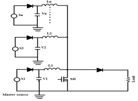
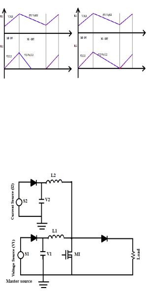
Figure 3: Multi input boost converter
Depending upon the characteristics of the sources connected to the converter it can be classified either as a voltage or a current source.
It is important to note that all the common renewable sources are unidirectional in nature and should be interfaced with a diode. When a current source is interfaced to the converter, a capacitor is used at the input terminal as can be seen from Fig. 3. This capacitor is required to meet the ripple requirements of the converter input current. When the source has a voltage source property, an input capacitor is avoided as it will invariably force the capacitor voltage to become equal to the master source terminal voltage due to duty constraint.
Modes of Operation
The different modes of operation of MISC converter is as outlined in Table I. All the modes given in Fig. 4 are valid if the basic constraint of output voltage being greater than input voltage is satisfied. Note that the output of the converter is connected to DC bus. The resistive load represents the load on the DC bus. All the operating modes explained below are very much dependent on the design of input inductor. This design philosophy will be covered in the next section.
Table 1: Modes of Operation
|
Modes of Operation |
|
Mode |
Master Source |
Slave source |
I |
Current Source |
Voltage Source |
II |
Current Source |
Current Source |
III |
Voltage Source |
Voltage Source |
IV |
Voltage Source |
Current Source |
7820 |
M. Karuppiah |
Mode I: Current Source And Voltage Source
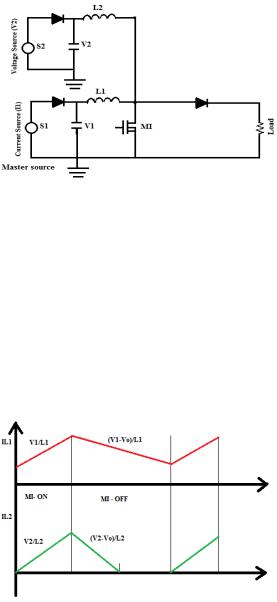
As shown in Fig. 4, when a current source is the master source and voltage source acts as a slave source there are two operating scenarios possible which is explained below as two sub-modes [2]. The duty ratio for these modes is fixed by the current source.
Figure 4: Current and voltage source inputs
1) Sub-Mode I-A: VI > V2:
When the input voltage of the master source is greater than that of the slave sources there will be 3 operating intervals for multi input boost converter, for a properly designed inductor, the current through the inductor (L1) of master source will be in current source. Therefore, for a similar or smaller value of inductor (L2), the current from slave source will be in voltage source. Assuming the L2 to be smaller is reasonable as the power rating of the slave source is not high. The inductor Current waveforms ILl and IL2 are as shown in Fig. 5.
Figure 5: Inductor current waveforms ILl and IL2
2) Sub-Mode I-B: VI ≤ V2:
When the master source terminal voltage is equal to that of the slave source, both the input currents are ideally in constant control mode. However, this may not be possible all the time, as the second source is assumed smaller. This may lead to the second
Improved DC Power Distribution With Multi-Input Single-Control Systems et.al. 7821
source working under current limit. Similarly, if slave source voltage is larger, for same duty cycle as the master, its current will invariably reach current limit. Therefore, all that can be said about this mode is that, in a practical development, the slave source works under current limit. The inductor current waveform IL2 indicated in Fig. 5 indicates the state of operation before the source current reaches its limit. When the slave source reaches current limit the inductor current waveform depend on the characteristics of source such as type of source, source impedance etc.
Mode 2: Current Source And Current Source
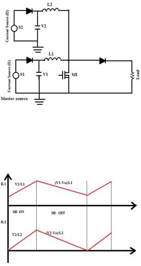
In this mode both inputs are current source is connected to multi input boost converter. It is shown in Fig. 6. The terminal voltages V1 and V2 will be forced to become equal by the duty ratio of the switch controlled by master source.
Figure 6: Current source inputs
For normal operation of MISC converter the inductor current waveforms are as shown in Fig. 7.
Figure 6: Inductor current waveforms ILl and IL2
7822 |
M. Karuppiah |
The normal operation of the converter is valid when input inductors and capacitors are selected properly. Ideally current IL I drawn from the source should be transferred only to the output and therefore this operating development is not efficient. To prevent this mode of operation the proper selection of Inductance and capacitance value is mandatory.
Mode 3: Voltage Source And Voltage Source
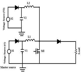
The inputs of MISC converter are connected to voltage sources as shown in Fig.7. In this mode of operation there are two sub-modes possible which are given below. The duty ratio for this mode is fixed by the master source.
Figure 7: Voltage source inputs
1) Sub-Mode III (A): VI > V2:
When input voltage of master source is greater than the slave source voltage there will be three operating intervals. The slave voltage source will be forced to operate in discontinuous current mode as the gain required is more [5]. As the power generated from the source is not very high, interfacing a separate converter for power extraction is not necessary and discontinuous current mode operation can be used for extraction of the available power. The input current waveform is as shown in Fig. 8.
2) Sub-Mode III (B): VI ≤ V2:
In this sub-mode of operation the input inductor currents I L I and I L2 ideally should operate in continuous current mode. As the duty ratio is fixed by master source, when input voltage of master source is less than or equal to the slave source voltage it will have a higher gain than required due to higher duty ratio. Output current from slave source increases till it reaches its current limit which is the equilibrium point of operation for the source [5]. The input inductor IL2 current waveform before the slave source reaches the current limit. When source reaches the current limit the operating waveform will depend of source characteristics such as source type, source impedance etc.
Improved DC Power Distribution With Multi-Input Single-Control Systems et.al. 7823
Figure 8: Inductor current waveforms IL1 and IL2
Mode 4: Voltage Source and Current Source
When a voltage source is the master source and a current source acts as a slave as shown in Fig. 9, the duty ratio of switch M1 is controlled by voltage source. The terminal voltage V2 of the current source will be forced to be equal to terminal voltage V1 and the current that can be supplied by the source is drawn from the source. There will be only two operating intervals.
Figure 9: Voltage and current source inputs
Under Normal operating conditions, when the input inductor and capacitors are selected properly, both the converters work in continuous current mode operation and the input inductor current waveforms are as shown in Fig. 10. Under high ripple operation which is caused when low value of inductance is selected and proper value of capacitance is not used to maintain the ripple the input current waveforms. This mode of operation is not preferred as the there is a negative portion of current which indicates the charging of the slave source input capacitor by master source which reduces the amount of current flowing to the output [6].