Материал: m083700e

Внимание! Если размещение файла нарушает Ваши авторские права, то обязательно сообщите нам

186 • CANopen

Network Communication

5.3.6 SYNC Monitoring

If the value of the communication cycle period is unequal to 0, monitoring is made with the first arrival of a SYNC message if the bus coupler is in the Operational status.

Failure of SYNC message:

If no SYNC message is received within the monitoring time (communication cycle period), this is signalled by a blink code. No status change occurs. In addition, an emergency message (Error Code: 0x8100, Error Register: 0x81, Additional Code: 00 04 00 00 00) is sent. The failure of the SYNC message will be displayed even if the MASTER provokes a status change.

It is only after the repeated receipt of the SYNC message in the OPERATIONAL status that the LEDs regain their normal operating status, and another emergency message (Error Code: 0x0000, Error Register: 0x81, Additional Code: 00 04 00 000 0) is sent to show that the SYNC monitoring functions again.

5.3.7 Node Guarding

The Node Guarding starts for the bus coupler when the first remote transmit request message (RTR) is received on the COB ID for the Node Guarding (0x700+Module-ID). If the bus coupler receives no corresponding message, the Node Guarding is not monitored by the bus coupler.

In the default setting, the Node Guarding is deactivated, because a 0 is entered in the corresponding indexes (0x100C = Guard-Time, 0x100D = Life Time Factor).

The NMT master polls the bus coupler at regular intervals. This interval is termed Guard-Time (Index 0x100C). The internal status of the bus coupler is in the reply message.

On the arrival of an RTR request without the Guard Time being set, the Node Guarding is not monitored, nevertheless the bus coupler replies with its internal status.

The states are coded as follows:

State: Value:

PRE-OPERATIONAL 127

OPERATIONAL 5

STOP

4

The Life-Time is the product of Guard-Time (Index 0x100C) and Life Time Factor (Index 0x100D).

WAGO-I/O-SYSTEM 750

CANopen

CANopen • 187

Network Communication

Failure of Node Guarding:

If no Node Guarding message is received with the life-time, this is shown by a blink code. In addition, an emergency message (Error Code: 0x8130, Error Register: 0x11, Additional Code: 0x00 04 00 000 0) is sent, the outputs are activated according to the objects 0x6206, 0x6207, 0x6443 and 0x6444, and the bus coupler changes to the pre-defined status according to object 0x67FE.

As soon as the Node Guarding protocol is recorded, another emergency message (Error Code: 0x0000, Error Register: 0x11, Additional Code: 00 04 00 000 0) is sent to show that the Node Guarding is reactivated, whereby the outputs and the bus coupler status remain unchanged.

It is possible to only use the Node Guarding protocol or the Heartbeat protocol. If the Heartbeat-Producer-Time is configured, the Heartbeat protocol is always used.

5.3.8 Heartbeat Monitoring

This protocol allows for monitoring the modules without having to use RTR frames.

The Heartbeat generator cyclically generates a message (time interval defined in object 0x1017), in which it transmits the module status. Transmission begins immediately after configuring the object 0x1017. The message can be evaluated by one or several Heartbeat consumers (object 0x1016). A maximum of 5 modules can be monitored. Monitoring starts with the first arrival of a Heartbeat message (separate for every module to be monitored).

Failure of the Heartbeat:

If no corresponding Heartbeat message is received within the configured time (object 0x1016), this is signalled by a blink code. In addition, an emergency message (Error Code: 0x8130, Error Register: 0x11, Additional Code: 0x00 05 KK 00 00, KK node number which has triggered EMCY) is sent. The outputs are activated according to objects 0x6206, 0x6207, 0x6443 and 0x6444 and the bus coupler changes to the status pre-defined according to 0x67FE.

As soon as the Heartbeat protocol is recorded, another emergency message (Error Code: 0x0000, Error Register: 0x11, Additional Code: 0x00 05 KK 00 00) is sent to display that Heartbeat is active again, whereby the outputs and the bus coupler status remain unchanged. If several modules are monitored, the blink code signalling the failure of the Heartbeat only stops after the previous Heartbeat has been resumed.

The only protocols to be used are the Node Guarding or the Heartbeat protocol. The Heartbeat protocol is used whenever the Heartbeat producer time is configured.

WAGO-I/O-SYSTEM 750

CANopen

188 • CANopen

Network Communication

5.3.9 Error Message (Emergency)

Emergency messages are always sent in the event of a critical error situation having occurred/overcome in the device, or if important information has to be communicated to other devices.

Structure and meaning of the entries in the emergency object are explained in the table “EMCY-CODE”, they are coded in the bus message in a Lowbyte / Highbyte order.

An emergency object is also sent, after an error is remedied (Error Code = 0x0000, the Error Register and the Additional Code behave as described in the table “EMCY-CODE”).

Following Power On an emergency object is sent if the loaded settings are the default settings. This occurs for two reasons:

No settings have yet been saved (Index 0x1010).

The saved setting were discarded by the bus coupler, because modules were connected or disconnected.

EMCY-CODE


Byte:

0

1

2

3

7


Name

Error


Error

Additional Code

Meaning


Code


Register


0x0000*

0x00

00 00 00 00 00


The "predefined error field" Index 0x1003 SubIdx. 0 set to


zero or all errors are cleared


0x5000*

0x81

00 01 00 00 00


Changed hardware configuration


after power on or reset Node / communication


The fieldbus coupler is be initialized, because no stored


configuration is available or the one available does not


coincide with the current configuration


0x5000*

0x81

00 02 00 00 00


Flash errors


An error has occurred when saving the configuration in


Flash.


0x5000*

0x81

00 03 PP LL SS

The programmed configuration does not coincide with the


actual one


PP: physical module slot where the error has occurred


LL: logic module slot where the error has occurred


SS: Cause of the error


0x5000*

0x81

00 09 00 00 00


Queue overflow for emergency messages


(can only occur when the inhibit time for emergency is


used)


0x5000*

0x81

00 0A 01 00 00


Max. number of Gateway modules exceeded, or max. size


of process image exceeded by Gateway modules


0x5000*

0x81

00 0A 02 00 00


Max. size of Mailbox exceeded


0x8100*

0x81

00 04 00 00 00


The time span between two SyncObjects is longer than the


communication_Cycle_Period


0x8110*

0x11

00 01 00 00 00


internal receive buffer overflow,


status change as defined in object 0x67FE. The outputs are


switched as defined in the Error-Mode/Value Objects


0x8110*

0x11

00 02 00 00 00


internal transmit buffer overflow,


status change as defined in object 0x67FE. The outputs are


switched as defined in the Error-Mode/Value objects


0x8120*

0x11

00 03 00 00 00


CAN Controller in Error Passive Mode


0x8130*

0x11

00 04 00 00 00


The time between two node guarding telegrams is greater


than Guard_Time * Life_Time_Faktor.


WAGO-I/O-SYSTEM 750

CANopen


CANopen

• 189


Network Communication


Byte:

0

1

2

3

7


Name

Error


Error

Additional Code

Meaning


Code


Register


0x8130*

0x11

00 05 KK 00 00

The time between two Heartbeat telegrams is greater than


configured


KK: Node that has tripped the time overflow


0x8210*

0x81

00 05 SS II NN

PDO was sent with a number of bytes smaller than that


configured in the communication profile.


The PDO data is discarded, i.e. the outputs remain un-


changed


SS:Set point value - configured value (i.e. in Index 0x1600


Sub-index 0)


II:Actual value - number of bytes sent


NN:Number of PDO (1..32)

0x8220*

0x81

00 08 SS II NN

PDO was sent with a number of bytes larger than that


configured in the communication profile.


Only the first n data is used (n = total length configured in


the object directory)


SS:Set point value - configured value (total length of all


valid and configured objects in bytes)


II:Actual value - number of bytes sent


NN:Number of PDO (1..32)

0xFF00*

0x81

00 06 PP 00 00

Internal bus error, change to the STOP status


- PP: Module position

0xFF00*

0x81

DD 07 PP SK NN

Diagnosis message


- DD: Diagnosis byte


- PP: Module position


- SK:Error status and channel number


- NN :Number of current module error

* Byte 0 = Lowbyte and Byte 1 = Highbyte

Example: Error Code 0x8220: Byte 0 = 0x20, Byte 1= 0x82

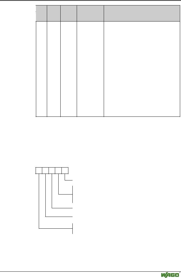
5.3.9.1 Diagnostic Message of I/O Modules

In the event of an error occurring in a module, which supports diagnostics, the diagnostic status is transmitted by means of the emergency message.

Design of the Additional Code of the Diagnosis message:

DD 07 PK SK NN

Number of current module errors

Bit 0,1 indicates the channel number of the module (channel 0..3)

Bit 2..7 reserved

Bit 8 indicates detected or cleared errors

Bit 8 = 1 Error detected, Bit 8 = 0 Error cleared

Position of the module

Identifier of the diagnosis message

Module specific diagnosis byte (analog modules) Module specific diagnosis byte (digital modules)

0 if the error have been cleared, i.e. byte SK Bit 8 = 0

Fig. 5-2: Design of Additional Code

g012423e

WAGO-I/O-SYSTEM 750

CANopen

190 • CANopen

Network Communication

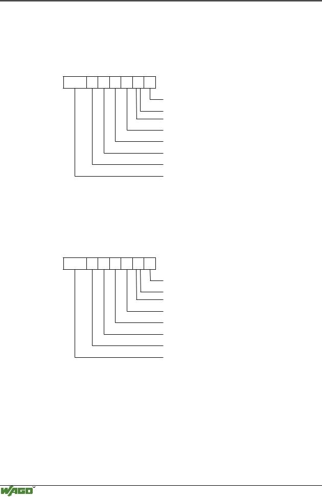
Example:

2 channel analog input module 750-465, connected at position14, current on channel 0 has more than 20mA.

Emergency Telegram

00 FF 81 42 07 0E 80 01

1 Error


Channel 0


Error detected


Module plugged at position 14


Diagnosis message


Current > 20,5 mA (see module description)


Error Register


Error Code


Fig. 5-3: Design of Emergency-Telegramm 1

g012424e

In addition to the first error, another error occurs on a 2 channel digital output module 750-506. A wire break on channel 1, the module is connected at position 17.

Emergency Telegram

00 FF 81 04 07 11 81 02

2 Error


Channel 1


Error detected


Module plugged at position 17


Diagnosis message


Bit 2 is set, wire breakage (see module description)


Error Register


Error Code


Fig. 5-4: Design of Emergency-Telegramm 2

g012425e

WAGO-I/O-SYSTEM 750

CANopen

Источник: https://studfile.net/preview/16369781/