Материал: m083700e

Внимание! Если размещение файла нарушает Ваши авторские права, то обязательно сообщите нам

CANopen • 141

Network Communication

5.3.3.3 Node Guarding Protocol

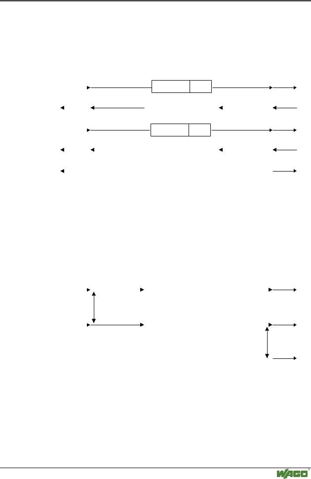
By means of Node Guarding, the NMT slave is cyclically requested via an RTR frame to send its current status. Additional toggling of a bit detects whether or not the NMT slave still operates correctly.


Node Guarding Protocol


NMT Master


NMT Slave

request


COB ID

Remote


indication


0x700+Node ID Frame


response

confimation


.7


.6

.0


Toggle-


Node State


Bit


request


COB ID


Remote


indication


0x700+Node ID Frame


confimation


response


.7


.6

.0


Toggle-


Node State


Bit


indication


indication


*if guarding error


Network Event*


Node Event*

Fig. 5-20: Node Guarding Protocol


g012419x

5.3.3.4 Heartbeat Protocol

This protocol allows monitoring without RTR frames. A heartbeat generator cyclically generates a heartbeat message received by n subscribers. The heartbeat message contains the coding of the current generator status.


Heartbeat Protocol

Heartbeat Producer


Heartbeat Consumer

request


indication(s)


0 … 7 s


Heartbeat


Producer


Time


request


indication(s)


0 … 7 s


Heartbeat


Consumer


Time

indication


Heartbeat


Event


Fig. 5-21: Heartbeat Protocol


g012420x

WAGO-I/O-SYSTEM 750

CANopen

142 • CANopen

Network Communication

5.3.3.5 Bootup Protocol

This protocol shows that the NMT slave has changed its status from INITIALIZING to PRE-OPERATIONAL. This is performed after a hardware/software reset or following the service reset code.

NMT Slave


NMT Master


0


request


indication


0


COB-ID = 1792 + Node-ID


Fig. 5-22: Bootup Protocol


g012421x

5.3.4 Object Directory

The object directory is the central point of a CANopen subscriber where all configuration information and data is stored and can be polled. The directory organization is by means of tables and contains three areas of CANopen objects:

Communication Profile Area (Index 0x1000 – 0x1FFF)

This profile contains all parameters relevant for CANopen communication. This area is identical for all CANopen subscribers.

Manufacturer Specific Profile Area (Index 0x2000 – 0x5FFF)

In this profile, each manufacturer can implement his own company specific objects.

Standardized Device Profile Area (Index 0x6000 – 0x9FFF)

This profile contains all objects which are assisted by a certain device profile. The bus coupler assists the device profile DS-401 (Device Profile for Generic I/O Modules)

In the object directory, a logical addressing scheme is used for the access to communication and device parameters, data and functions. Each entry into the directory is identified by a 16 bit index which indicates the row address of the table. A maximum of 65536 entries are permitted.

If an object is composed of several components, the components are identified by means of an 8 bit sub-index. The sub-index indicates the individual column address of the table allowing a maximum of 256 entries.

WAGO-I/O-SYSTEM 750

CANopen

CANopen • 143

Network Communication

Each entry consists of:

an object name describing the object function,

a data type attribute defining the data type of the entry, and

an access attribute indicating whether the entry is only read, only write or read and write.

The sub-index 0 indicates the max. number of the following sub-indexes. The data is coded in the following sub-indexes.

Index (hexadecimal)

Object

0x0000


Not used


0x0001

– 0x001F

Static data types


0x0020

– 0x003F

Complex data types


0x0040

– 0x005F

Manufacturer specific data types


0x0060

– 0x007F

Profile specific static data types


0x0080

– 0x009F

Profile specific complex data types


0x00A0 – 0x0FFF

Reserved


0x1000

– 0x1FFF

Communication profile (DS-301)


0x2000

– 0x5FFF

Manufacturer specific parameters


0x6000

– 0x9FFF

Parameters from standardized device profiles


0xA000 – 0xFFFF

Reserved


Table 5-2: Structure of the CANopen object directory

The object directory structure is designed for the worst case. Object entries that cannot be used because of the connected module configuration are deactivated.

WAGO-I/O-SYSTEM 750

CANopen

144 • CANopen

Network Communication

5.3.4.1 Initialization

The connected module configuration is determined following power On.

If a customer-specific configuration was saved and if the currently connected module configuration coincides with the one last saved, the object directory with this saved configuration will be initialized.

In every other case, object directory will be assigned a default configuration.

5.3.4.1.1 Default configuration 5.3.4.1.1.1Initialization Communication Profile Area

All objects of this profile assisted by the bus coupler are initialized according to the default values of DS 301 (CANopen Application Layer and Communication Profile).

Entry of the default mapping parameters:

Pre-assignment of the mapping parameters depends on the device profile used. The bus coupler assists the DS 401 profile, and as such the process described there is used. The first 4 Rx-/TxPDOs are defined as default PDOs. If more inputs/outputs exist at the bus coupler than can be covered with the default PDOs, from Rx-/TxPDO 5 all remaining I/Os are entered. First all digital, then all analog I/Os are entered. If more than 64 digital I/Os per input/output are available, a continuation is only made with PDO 5, even if no analog modules exist. PDO 2 to 4 will then remain unused. Furthermore, only one data type is used as a default entry for a PDO, in other words, if a 3 byte and a 4 byte module exists, then a default is entered for each of the 2 PDOs.

1. RxPDO:

contains maximum the first 8x8 digital outputs. If no digital outputs exist, the sub index 0 has the default value 0, and this PDO is not used with its default value.

Idx

S-Idx

Description

Default Value

0x1600

0

Number of mapped objects

None, possible values:


0: no digital output block


1..8: 1..8 digital output


blocks


1

1. mapped digital output block

0x6200 01 08


2

2. mapped digital output block

0x6200 02 08


:

:

:


8

8. mapped digital output block

0x6200 08 08


WAGO-I/O-SYSTEM 750

CANopen

CANopen • 145

Network Communication

2. RxPDO:

contains max. the 1st to 4th 16 bit analog output. If no 16 bit analog outputs exist, the sub index 0 has the default value 0, and this PDO is not used with its default value.

Idx

S-Idx

Description

Default Value

0x1601

0

Number of mapped objects

None, possible values:


0: no analog output


1..4: 1..4 analog outputs


1

1. mapped 16 bit analog output

0x6411 01 10


2

2. mapped 16 bit analog output

0x6411 02 10


3

3. mapped 16 bit analog output

0x6411 03 10


4

4. mapped 16 bit analog output

0x6411 04 10


3. RxPDO:

contains maximum the 5th to 8th bit analog output. If more than 4 16 bit analog outputs exist, the sub index 0 has the default value 0, and this PDO is not used with its default value.

Idx

S-Idx

Description

Default Value

0x1602

0

Number of mapped objects

None, possible values:


0: no analog output


1..4: 1..4 analog outputs


1

5. mapped 16 bit analog output

0x6411 05 10


2

6. mapped 16 bit analog output

0x6411 06 10


3

7. mapped 16 bit analog output

0x6411 07 10


4

8. mapped 16 bit analog output

0x6411 08 10


4. RxPDO:

contains maximum the 9th to 12th 16 bit analog output. If not more than 8 16 bit analog outputs exist, the sub index 0 has the default value 0, and this PDO is not used with its default value.

Idx

S-Idx

Description

Default Value

0x1603

0

Number of mapped objects

None, possible values:


0: no analog output


1..4: 1..4 analog outputs


1

9. mapped 16 bit analog output

0x6411

09 10


2

10. mapped 16 bit analog output

0x6411

0A 10


3

11. mapped 16 bit analog output

0x6411

0B 10


4

12. mapped 16 bit analog output

0x6411

0C 10


WAGO-I/O-SYSTEM 750

CANopen

Источник: https://studfile.net/preview/16369781/