Материал: 9635

DISCRETE SEMICONDUCTORS
BA792
Band-switching diode
Product specification |
|
1996 Mar 13 |
|||||
File under Discrete Semiconductors, SC01 |
|
|
|
|
|
|
|
|
|
|
|
|
|
|
|
|
|
|
|
|
|
|
|
|
|
|
|
|
|
|
|
Philips Semiconductors |
Product specification |
|
|
Band-switching diode |
BA792 |
|
|
|
|
FEATURES
∙Ceramic SMD package
∙Low diode capacitance: max. 1.1 pF
∙Low diode forward resistance: max. 0.7 Ω.
APPLICATIONS
∙Low loss band-switching in VHF television tuners
∙Surface mount high-speed switching circuits.
DESCRIPTION
Planar, high performance band-switching diode in a small ceramic SOD110 SMD package.
LIMITING VALUES
handbook, 4 columns |
|
|
cathode mark |
|
k |
k |
a |
||
a |
bottom view |
side view |
top view |
MAM139 |
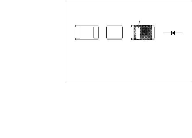
Marking code: L8.
Fig.1 Simplified outline (SOD110) and symbol.
In accordance with the Absolute Maximum Rating System (IEC 134).
SYMBOL |
PARAMETER |
MIN. |
MAX. |
UNIT |
|
|
|
|
|
VR |
continuous reverse voltage |
− |
35 |
V |
IF |
continuous forward current |
− |
100 |
mA |
Tstg |
storage temperature |
−65 |
+150 |
°C |
Tj |
junction temperature |
− |
150 |
°C |
1996 Mar 13 |
2 |
Philips Semiconductors |
|
Product specification |
||
|
|
|
|
|
Band-switching diode |
|
|
BA792 |
|
|
|
|
|
|
ELECTRICAL CHARACTERISTICS |
|
|
|
|
Tj = 25 °C unless otherwise specified. |
|
|
|
|
|
|
|
|
|
SYMBOL |
PARAMETER |
CONDITIONS |
MAX. |
UNIT |
|
|
|
|
|
VF |
forward voltage |
IF = 100 mA |
1.1 |
V |
IR |
reverse current |
VR = 20 V |
10 |
nA |
|
|
VR = 20 V; Tamb = 75 °C |
1 |
μA |
Cd |
diode capacitance |
VR = 3 V; f = 1 to 100 MHz; note 1 |
1.1 |
pF |
rD |
diode forward resistance |
IF = 3 mA; f = 200 MHz; note 1 |
0.7 |
Ω |
Note
1. Guaranteed on AQL basis: inspection level S4, AQL 1.0.
THERMAL CHARACTERISTICS
SYMBOL |
PARAMETER |
|
CONDITIONS |
VALUE |
UNIT |
|
|
|
|
|
|
Rth j-a |
thermal resistance from junction to ambient |
note 1 |
|
315 |
K/W |
Note
1. Device mounted on a printed-circuit board measuring 11 × 25 × 1.6 mm.
MOUNTING
Reflow soldering
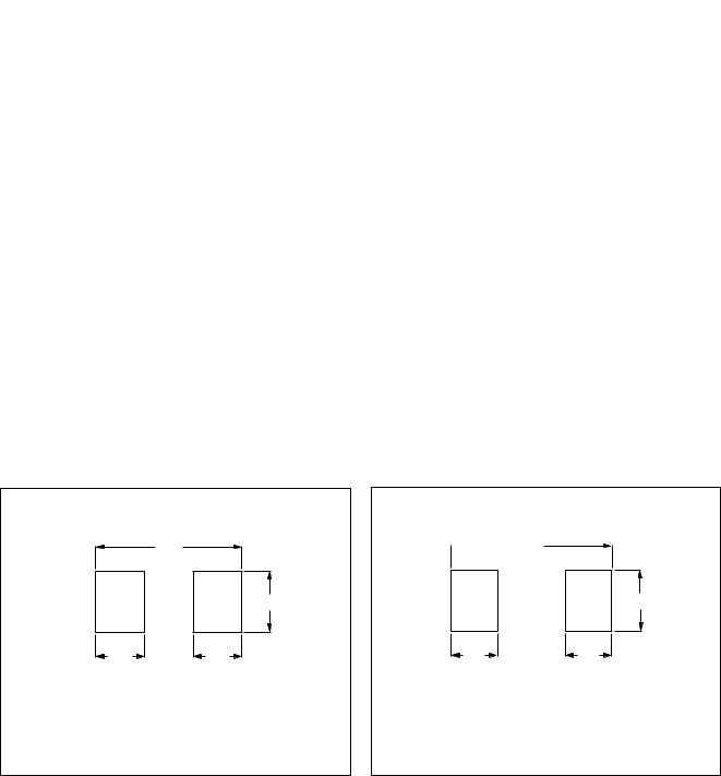
Follow standard reflow soldering techniques to ensure correct application of solder paste and placement of the SOD110 package (see Fig.2).
Wave soldering
Before wave soldering, attach SOD110 packages to the printed-circuit boards using a small dot of thermo-setting epoxy or UV-curing adhesive centred between the soldering lands (see Fig.3).
handbook, halfpage |
3.00 |
|
|
|
|
|
|
1.25 |
1.00 |
1.00 |
MGC119 |
Dimensions in mm.
Fig.2 SOD110 reflow soldering pattern.
handbook, halfpage 3.40
3.40
|
|
1.25 |
1.10 |
1.10 |
MGC126 |
Dimensions in mm.
Fig.3 SOD110 wave soldering pattern.
1996 Mar 13 |
3 |
Philips Semiconductors |
Product specification |
|
|
Band-switching diode |
BA792 |
|
|
PACKAGE OUTLINE |
|
cathode  mark
mark
2.10
1.90

 1.6 max
MSA323 - 1
1.40
1.10


 0.1
0.1
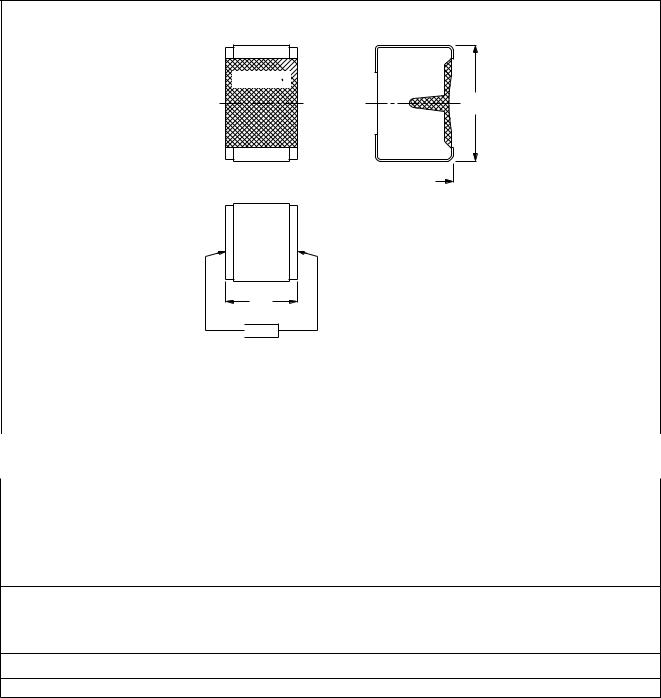
Dimensions in mm.
Marking band indicates the cathode.
|
Fig.4 SOD110. |
|
|
DEFINITIONS |
|
|
|
Data sheet status |
|
|
|
Objective specification |
This data sheet contains target or goal specifications for product development. |
|
|
Preliminary specification |
This data sheet contains preliminary data; supplementary data may be published later. |
|
|
Product specification |
This data sheet contains final product specifications. |
|
|
Limiting values |
|
Limiting values given are in accordance with the Absolute Maximum Rating System (IEC 134). Stress above one or more of the limiting values may cause permanent damage to the device. These are stress ratings only and operation of the device at these or at any other conditions above those given in the Characteristics sections of the specification is not implied. Exposure to limiting values for extended periods may affect device reliability.
Application information
Where application information is given, it is advisory and does not form part of the specification.
LIFE SUPPORT APPLICATIONS
These products are not designed for use in life support appliances, devices, or systems where malfunction of these products can reasonably be expected to result in personal injury. Philips customers using or selling these products for use in such applications do so at their own risk and agree to fully indemnify Philips for any damages resulting from such improper use or sale.
1996 Mar 13 |
4 |
Philips Semiconductors |
Product specification |
|
|
Band-switching diode |
BA792 |
|
|
|
NOTES |
1996 Mar 13 |
5 |