Материал: 271001
M27C1001
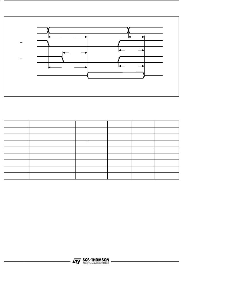
Figure 5. Read Mode AC Waveforms
A0-A16 |
VALID |
|
|
tAVQV |
tAXQX |
E |
|
tGLQV |
tEHQZ |
|
|
G |
|
tELQV |
tGHQZ |
|
|
Q0-Q7 |
Hi-Z |
DATA OUT |
|
|
AI00713 |
Table 8. Programming Mode DC Characteristics (1)
(TA = 25 °C; VCC = 6.25V ± 0.25V; VPP = 12.75V ± 0.25V)
Symbol |
Parameter |
Test Condition |
Min |
Max |
Unit |
ILI |
Input Leakage Current |
VIL ≤ VIN ≤ VIH |
|
±10 |
μA |
ICC |
Supply Current |
|
|
50 |
mA |
IPP |
Program Current |
E = VIL |
|
50 |
mA |
VIL |
Input Low Voltage |
|
±0.3 |
0.8 |
V |
VIH |
Input High Voltage |
|
2 |
VCC + 0.5 |
V |
VOL |
Output Low Voltage |
IOL = 2.1mA |
|
0.4 |
V |
VOH |
Output High Voltage TTL |
IOH = ±400μA |
2.4 |
|
V |
VID |
A9 Voltage |
|
11.5 |
12.5 |
V |
Note: 1. VCC must be applied simultaneously with or before VPP and removed simultaneously or after VPP.
6/15
|
|
|
|
|
|
M27C1001 |
Table 9. Programming Mode AC Characteristics (1) |
|
|
|
|||
(TA = 25 °C; VCC = 6.25V ± 0.25V; VPP = 12.75V ± 0.25V) |
|
|
|
|||
Symbol |
Alt |
Parameter |
Test Condition |
Min |
Max |
Unit |
tAVPL |
tAS |
Address Valid to Program Low |
|
tQVPL |
tDS |
Input Valid to Program Low |
|
tVPHPL |
tVPS |
VPP High to Program Low |
|
tVCHPL |
tVCS |
VCC High to Program Low |
|
tELPL |
tCES |
Chip Enable Low to |
|
Program Low |
|||
|
|
||
tPLPH |
tPW |
Program Pulse Width |
|
tPHQX |
tDH |
Program High to Input |
|
Transition |
|||
|
|
||
tQXGL |
tOES |
Input Transition to Output |
|
Enable Low |
|||
|
|
||
tGLQV |
tOE |
Output Enable Low to |
|
Output Valid |
|||
|
|
||
(2) |
tDFP |
Output Enable High to |
|
tGHQZ |
Output Hi-Z |
||
|
|
||
tGHAX |
tAH |
Output Enable High to |
|
Address Transition |
|||
|
|
Notes: 1. VCC must be applied simultaneously with or before VPP 2. Sampled only, not 100% tested.
2 |
|
μs |
2 |
|
μs |
2 |
|
μs |
2 |
|
μs |
2 |
|
μs |
95 |
105 |
μs |
2 |
|
μs |
2 |
|
μs |
|
100 |
ns |
0 |
130 |
ns |
0 |
|
ns |
and removed simultaneously or after VPP.
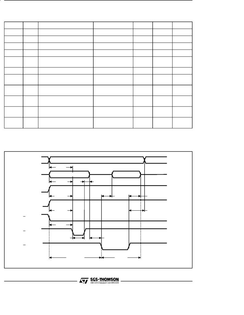
Figure 6. Programming and Verify Modes AC Waveforms
A0-A16 |
|
VALID |
|
|
|
|
|
|
tAVPL |
|
|
Q0-Q7 |
DATA IN |
DATA OUT |
|
|
tQVPL |
tPHQX |
|
VPP |
|
|
|
|
tVPHPL |
tGLQV |
tGHQZ |
VCC |
|
|
|
|
tVCHPL |
|
tGHAX |
E |
|
|
|
|
tELPL |
|
|
P |
|
|
|
|
tPLPH |
tQXGL |
|
G |
|
|
|
|
PROGRAM |
VERIFY |
|
|
|
|
AI00714 |
7/15
M27C1001
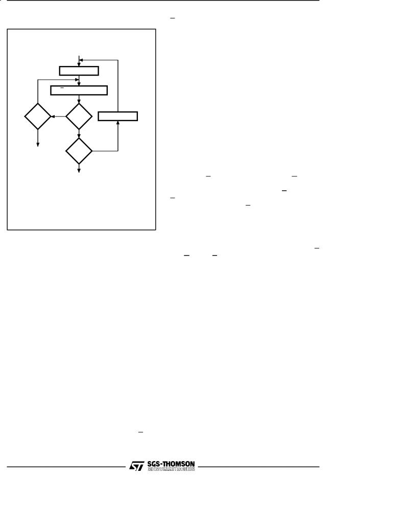
Figure 7. Programming Flowchart
|
VCC = 6.25V, VPP = 12.5V |
|
|
n = 0 |
|
|
P = 100μs Pulse |
|
NO |
|
|
++n |
NO |
++ Addr |
= 25 |
VERIFY |
|
|
|
|
YES |
YES |
|
FAIL |
Last |
NO |
Addr |
|
|
|
|
|
YES
CHECK ALL BYTES 1st: VCC = 6V 2nd: VCC = 4.2V
AI00715B
DEVICE OPERATION (cont'd)
The associated transient voltage peaks can be suppressed by complying with the two line output control and by properly selected decoupling capacitors. It is recommended that a 0.1μF ceramic capacitor be used on every device between VCC and VSS. This should be a high frequency capacitor of low inherent inductance and should be placed as close to the device as possible. In addition, a 4.7μF bulk electrolytic capacitor should be used between VCC and VSS for every eight devices. The bulk capacitor should be located near the power supply connection point. The purpose of the bulk capacitor is to overcome the voltage drop caused by the inductive effects of PCB traces.
Programming
When delivered (and after each erasure for UV EPROM), all bits of the M27C1001 are in the '1' state. Data is introduced by selectively programming '0' into the desired bit locations. Although only '0' will be programmed, both '1' and '0' can be present in the data word. The only way to change a '0' to a '1' is by die exposition to ultraviolet light (UV EPROM). The M27C1001 is in the programming mode when Vpp input is at 12.75V, and E and
P are at TTL-low. The data to be programmed is applied 8 bits in parallel to the data output pins. The levels required for the address and data inputs are TTL. VCC is specified to be 6.25V ± 0.25V.
PRESTO II Programming Algorithm
PRESTO II Programming Algorithm allows the whole array to be programmed, with a guaranteed margin, in a typical time of 13 seconds. Programming with PRESTO II involves in applying a sequence of 100μs program pulses to each byte until a correct verify occurs. During programming and verify operation, a MARGIN MODE circuit is automatically activated in order to guarantee that each cell is programmed with enough margin. No overprogram pulse is applied since the verify in MARGIN MODE provides necessary margin to each programmed cell.
Program Inhibit
Programming of multiple M27C1001s in parallel with different data is also easily accomplished. Except for E, all like inputs including G of the parallel M27C1001 may be common. A TTL low level pulse applied to a M27C1001's E input, with P low and VPP at 12.75V, will program that M27C1001. A high level E input inhibits the other M27C1001s from being programmed.
Program Verify
A verify (read) should be performed on the programmed bits to determine that they were correctly programmed. The verify is accomplished with E
and G at VIL, P at VIH, VPP at 12.75V and VCC at 6.25V.
Electronic Signature
The Electronic Signature mode allows the reading out of a binary code from an EPROM that will identify its manufacturer and type. This mode is intended for use by programming equipment to automatically match the device to be programmed with its corresponding programming algorithm. This mode is functional in the 25°C ± 5°C ambient temperature range that is required when programming the M27C1001. To activate this mode, the programming equipment must force 11.5V to 12.5V on address line A9 of the M27C1001, with VPP=VCC=5V. Two identifier bytes may then be sequenced from the device outputs by toggling address line A0 from VIL to VIH. All other address lines must be held at VIL during Electronic Signature mode.
Byte 0 (A0=VIL) represents the manufacturer code and byte 1 (A0=VIH) the device identifier code. For the SGS-THOMSON M27C1001, these two identifier bytes are given in Table 4 and can be read-out on outputs Q0 to Q7.
8/15
M27C1001
ERASURE OPERATION (applies to UV EPROM)
The erasure characteristics of the M27C1001 is such that erasure begins when the cells are exposed to light with wavelengths shorter than approximately4000 Å. It should be notedthat sunlight and some type of fluorescent lamps have wavelengths in the 3000-4000 Å range. Research shows that constant exposure to room level fluorescent lighting could erase a typical M27C1001 in about 3 years, while it would take approximately 1 week to cause erasure when exposed to direct sunlight. If the M27C1001 is to be exposed to these types of lighting conditions for extended periods of
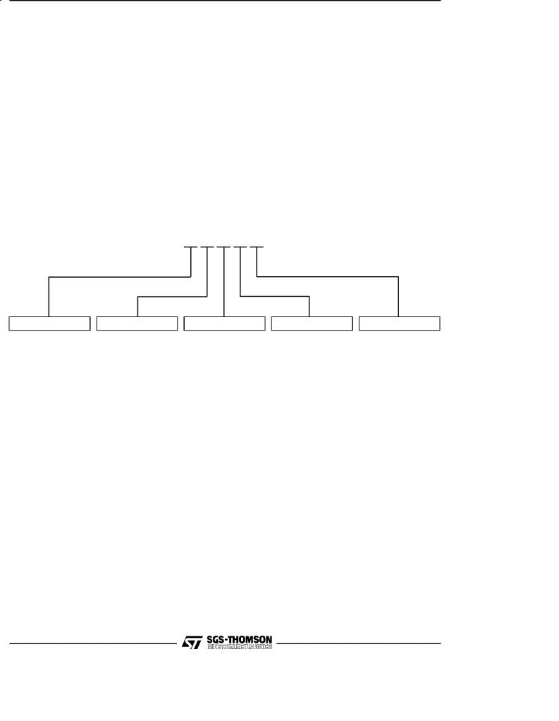
ORDERING INFORMATION SCHEME
time, it is suggested that opaque labels be put over the M27C1001 window to prevent unintentional erasure. The recommended erasure procedure for the M27C1001 is exposure to short wave ultraviolet light which has a wavelength of 2537 Å. The integrated dose (i.e. UV intensity x exposure time) for erasure should be a minimum of 15 W-sec/cm2. The erasure time with this dosage is approximately 15 to 20 minutes using an ultraviolet lamp with 12000 uW/cm2 power rating. The M27C1001 should be placed within 2.5 cm (1 inch) of the lamp tubes during the erasure. Some lamps have a filter on their tubes which should be removed before erasure.
Example: M27C1001 -70 X C 1 TR
|
Speed |
VCC Tolerance |
|
Package |
Temperature Range |
|
Option |
|||
-45 |
45 ns |
X |
± 5% |
F |
FDIP32W |
1 |
0 to 70 °C |
X |
Additional |
|
-55 |
55 ns |
blank |
± 10% |
L |
LCCC32W |
3 |
±40 to 125 °C |
|
Burn-in |
|
TR |
Tape & Reel |
|||||||||
-60 |
60 ns |
|
|
B |
PDIP32 |
6 |
±40 to 85 °C |
|||
|
|
|
Packing |
|||||||
|
|
|
|
|
|
|
|
|
||
-70 |
70 ns |
|
|
C |
PLCC32 |
|
|
|
|
|
-80 |
80 ns |
|
|
N |
TSOP32 |
|
|
|
|
|
-90 |
90 ns |
|
|
|
8 x 20mm |
|
|
|
|
|
|
|
|
|
|
|
|
|
|||
-10 |
100 ns |
|
|
|
|
|
|
|
|
|
-12 |
120 ns |
|
|
|
|
|
|
|
|
|
-15 |
150 ns |
|
|
|
|
|
|
|
|
|
-20 |
200 ns |
|
|
|
|
|
|
|
|
|
-25 |
250 ns |
|
|
|
|
|
|
|
|
|
For a list of available options (Speed, VCC Tolerance,Package, etc...) refer to the current Memory Shortform catalogue.
For further information on any aspect of this device, please contact SGS-THOMSON Sales Office nearest to you.
9/15
M27C1001
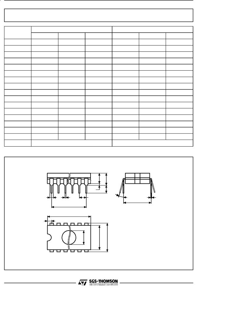
FDIP32W - 32 pin Ceramic Frit-seal DIP, with window
Symb |
|
mm |
|
|
inches |
|
|
Typ |
Min |
Max |
Typ |
Min |
Max |
||
|
|||||||
A |
|
|
5.71 |
|
|
0.225 |
|
A1 |
|
0.50 |
1.78 |
|
0.020 |
0.070 |
|
A2 |
|
3.90 |
5.08 |
|
0.154 |
0.200 |
|
B |
|
0.40 |
0.55 |
|
0.016 |
0.022 |
|
B1 |
|
1.27 |
1.52 |
|
0.050 |
0.060 |
|
C |
|
0.22 |
0.31 |
|
0.009 |
0.012 |
|
D |
|
|
42.78 |
|
|
1.684 |
|
E |
|
15.40 |
15.80 |
|
0.606 |
0.622 |
|
E1 |
|
14.50 |
14.90 |
|
0.571 |
0.587 |
|
e1 |
2.54 |
± |
± |
0.100 |
± |
± |
|
e3 |
38.10 |
± |
± |
1.500 |
± |
± |
|
eA |
|
16.17 |
18.32 |
|
0.637 |
0.721 |
|
L |
|
3.18 |
4.10 |
|
0.125 |
0.161 |
|
S |
|
1.52 |
2.49 |
|
0.060 |
0.098 |
|
|
9.65 |
± |
± |
0.380 |
± |
± |
|
α |
|
4° |
15° |
|
4° |
15° |
|
N |
|
32 |
|
|
32 |
|
FDIP32W
|
|
A2 |
A |
|
|
|
A1 |
L |
|
B1 |
B |
e1 |
α |
C |
|
e3 |
|
|
eA |
|
|
|
|
|
|
D |
|
|
|
|
S |
|
|
|
|
N |
|
|
|
|
|
E1 |
E |
|
|
1 |
|
|
|
FDIPW-a
Drawing is not to scale
10/15